Solar battery box in an ammo can
Hi, I’m Keegan, callsign KM6PNI! Welcome to my new blog. It’s been a long time since I blogged, and I decided to get back into it by documenting some of my amateur radio projects. For my first post, I will show off a solar-charging battery box that I built for portable radio adventures and emergency power.
Capabilities
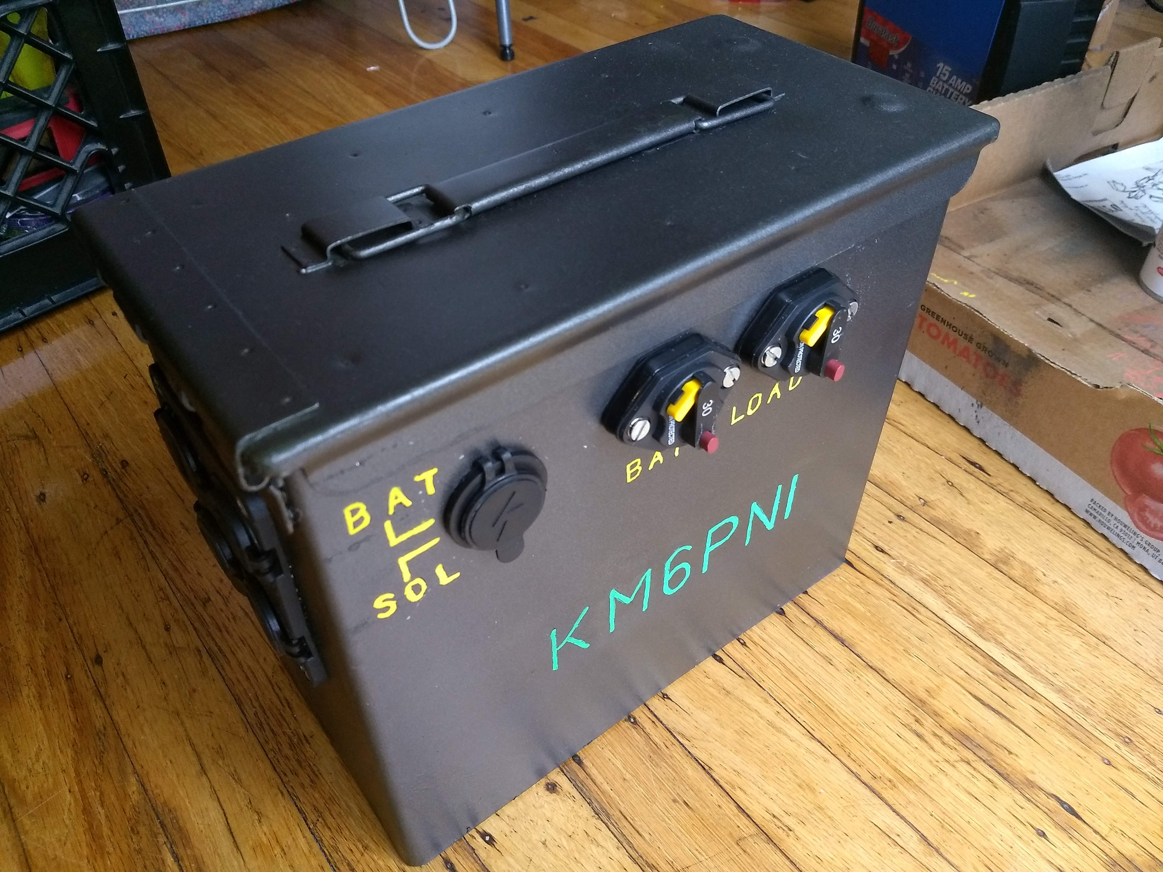
I will describe the internals later, but basically this is a lead-acid battery and a solar charge controller, installed in a military-surplus ammo can.
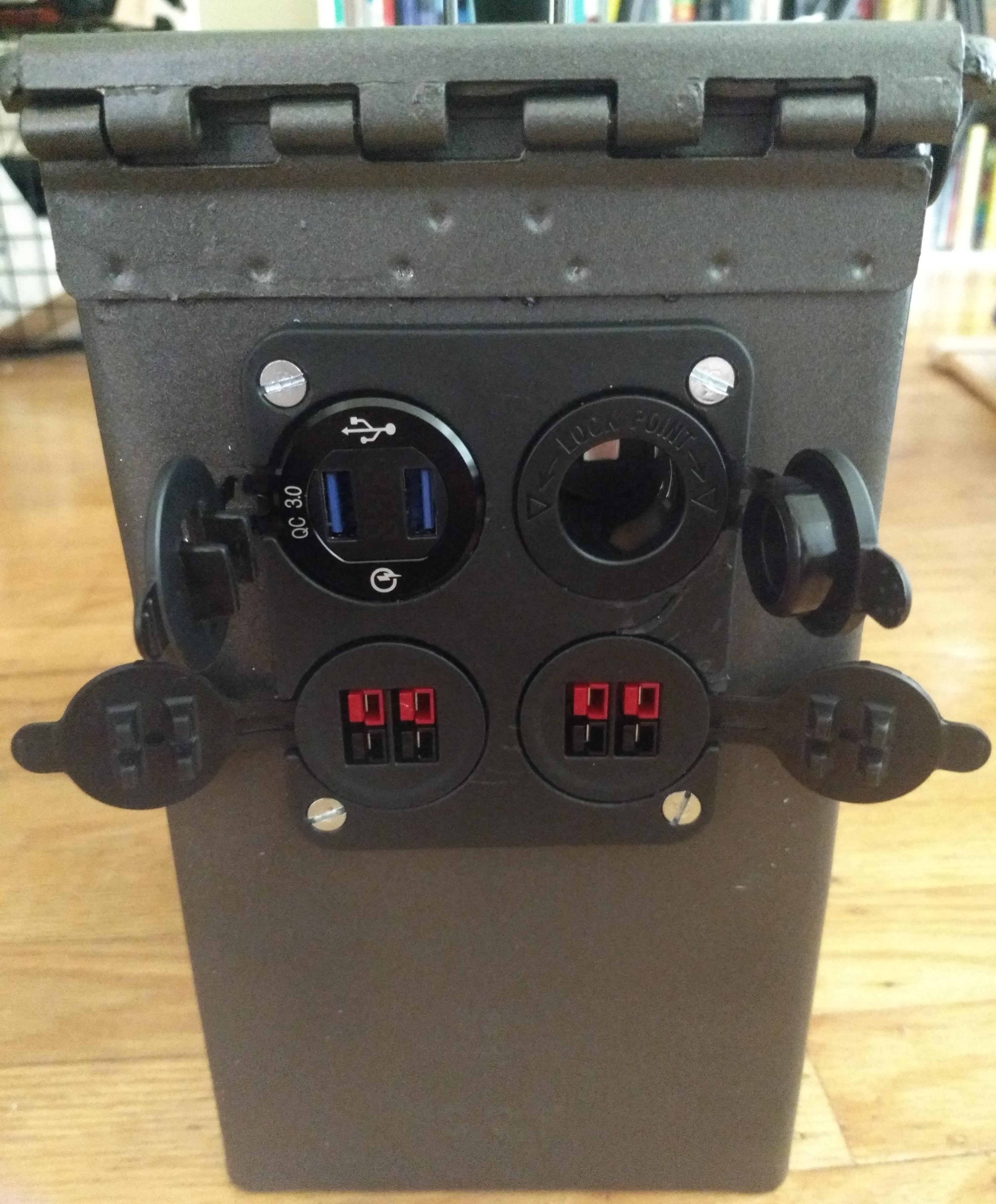
It provides 12 volt power through four Powerpole connectors, as well as a car accessory socket. It also provides two USB Quick Charge ports. Between the USB ports is a built-in voltmeter.
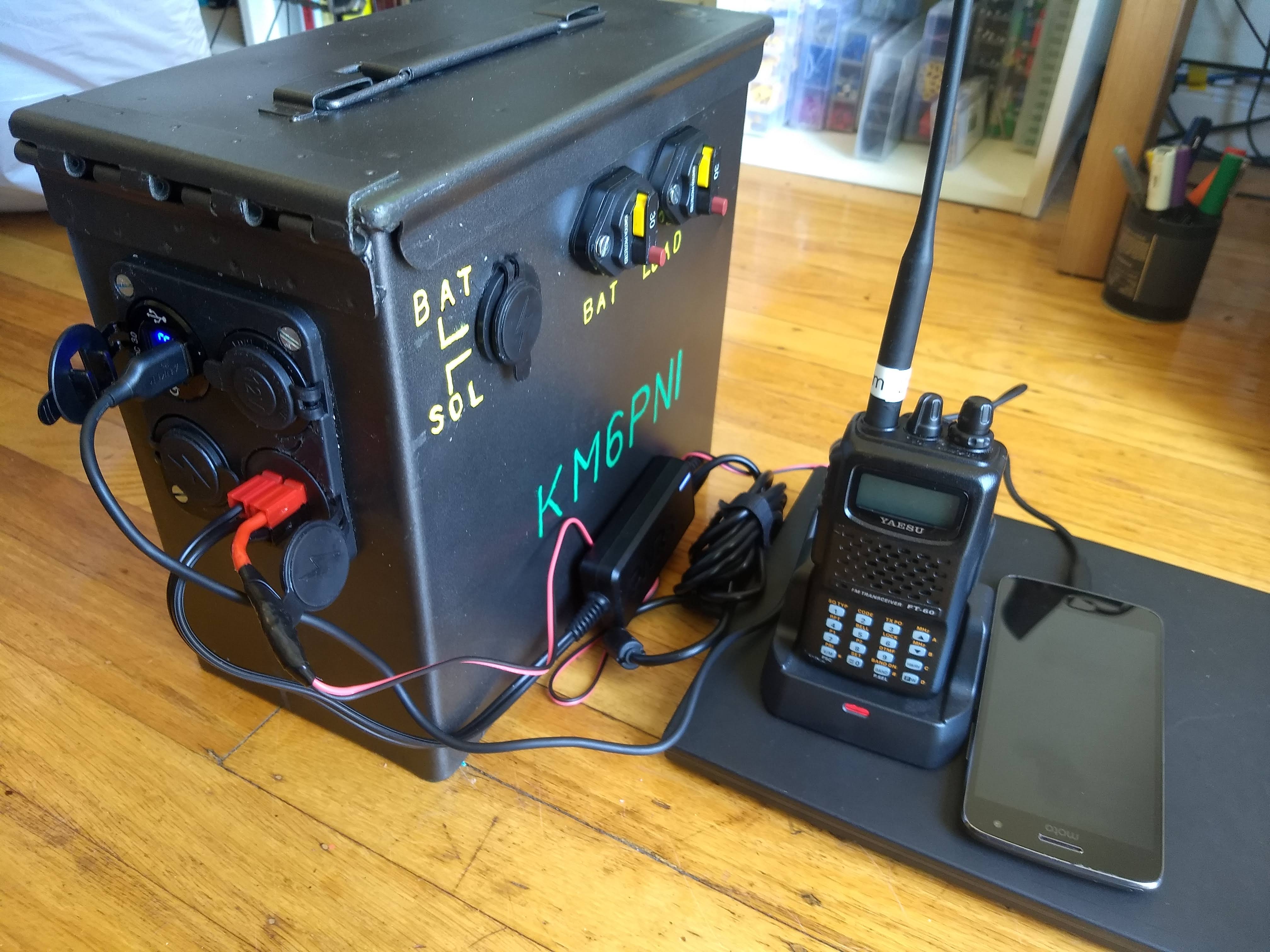
Here you can see the battery charging my phone, my laptop, and my Yaesu FT-60R handheld radio. For the laptop, I’m using a USB-C car charger brick, which I modified with a Powerpole connector. The FT-60R charges through a Powerpole-to-barrel-jack cable that I made, and the phone is ordinary USB Quick Charge.
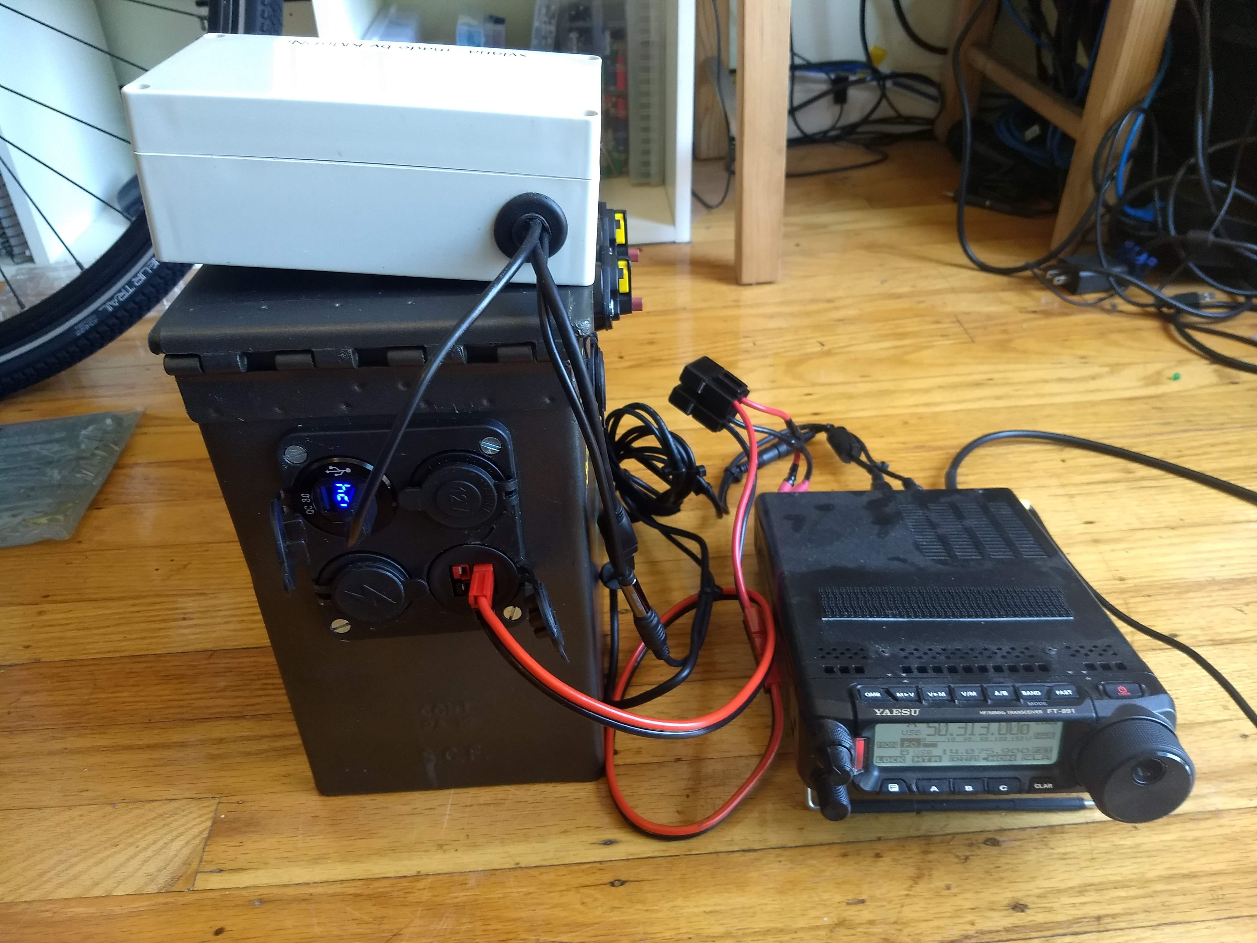
Here the box is powering my Yaesu FT-891 and a Raspberry Pi 3 (in the plastic box at top). The RPi interfaces with the radio so I can send and receive digital messages. With this equipment plus an antenna, I can send a message around the world, using no infrastructure and only a few watts of power. I’ll write another article about the RPi digital-mode setup at some point.
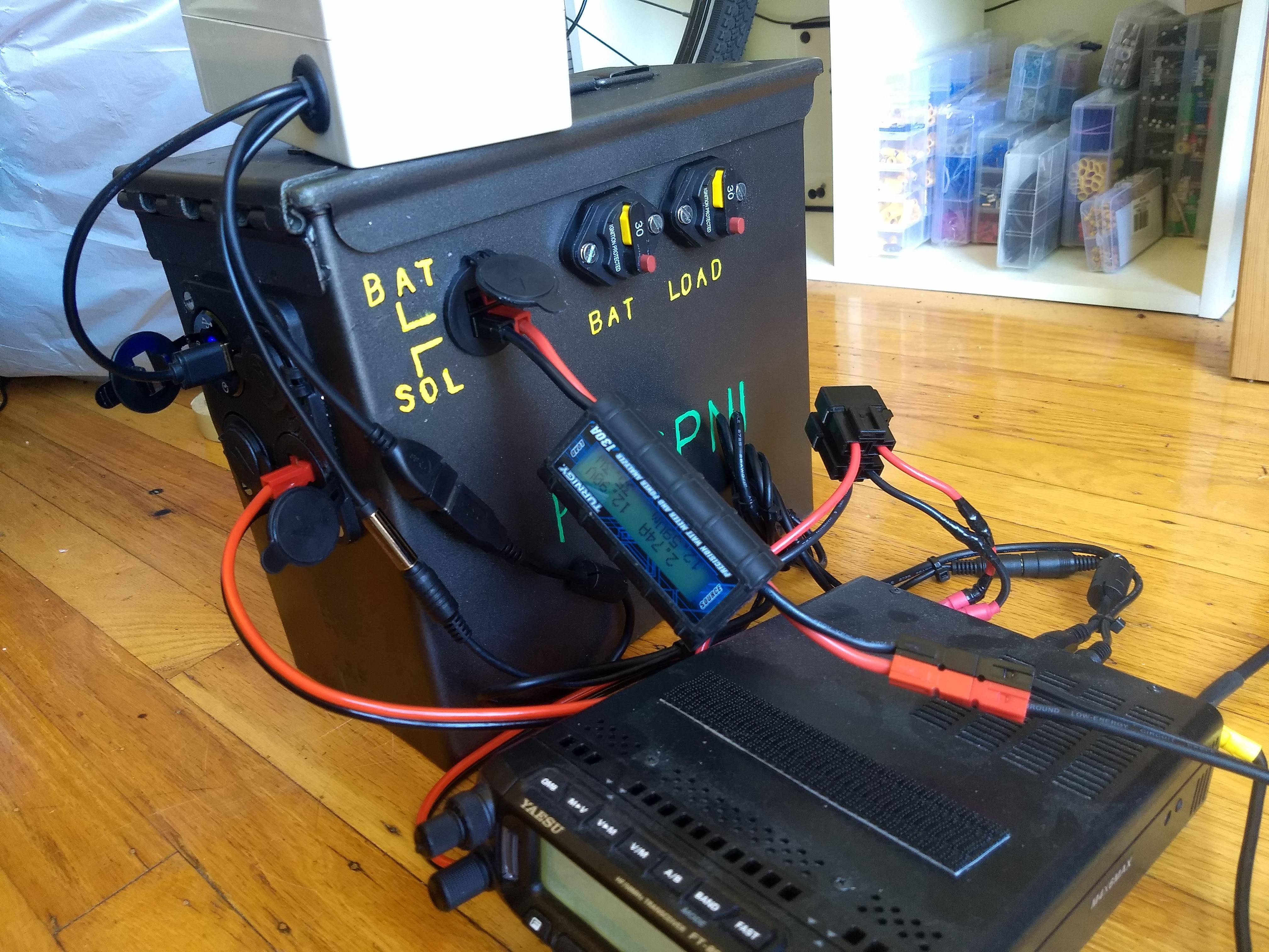
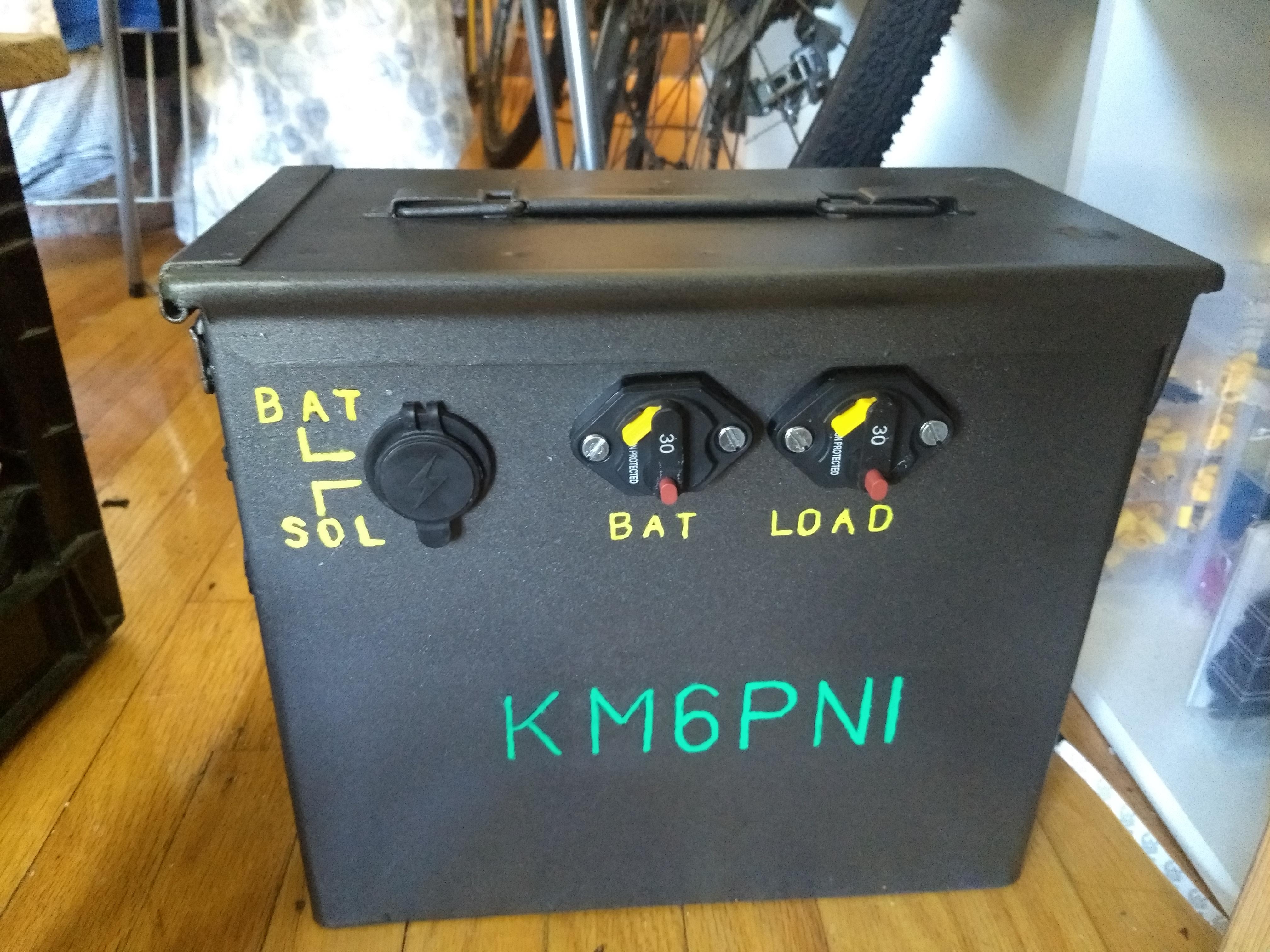
On the right side of the box, there are two additional Powerpole connectors and a pair of circuit breakers (full wiring diagram below). These connectors are used to charge the battery. Here I have a 12V solar panel plugged in to the connector marked “SOL”.
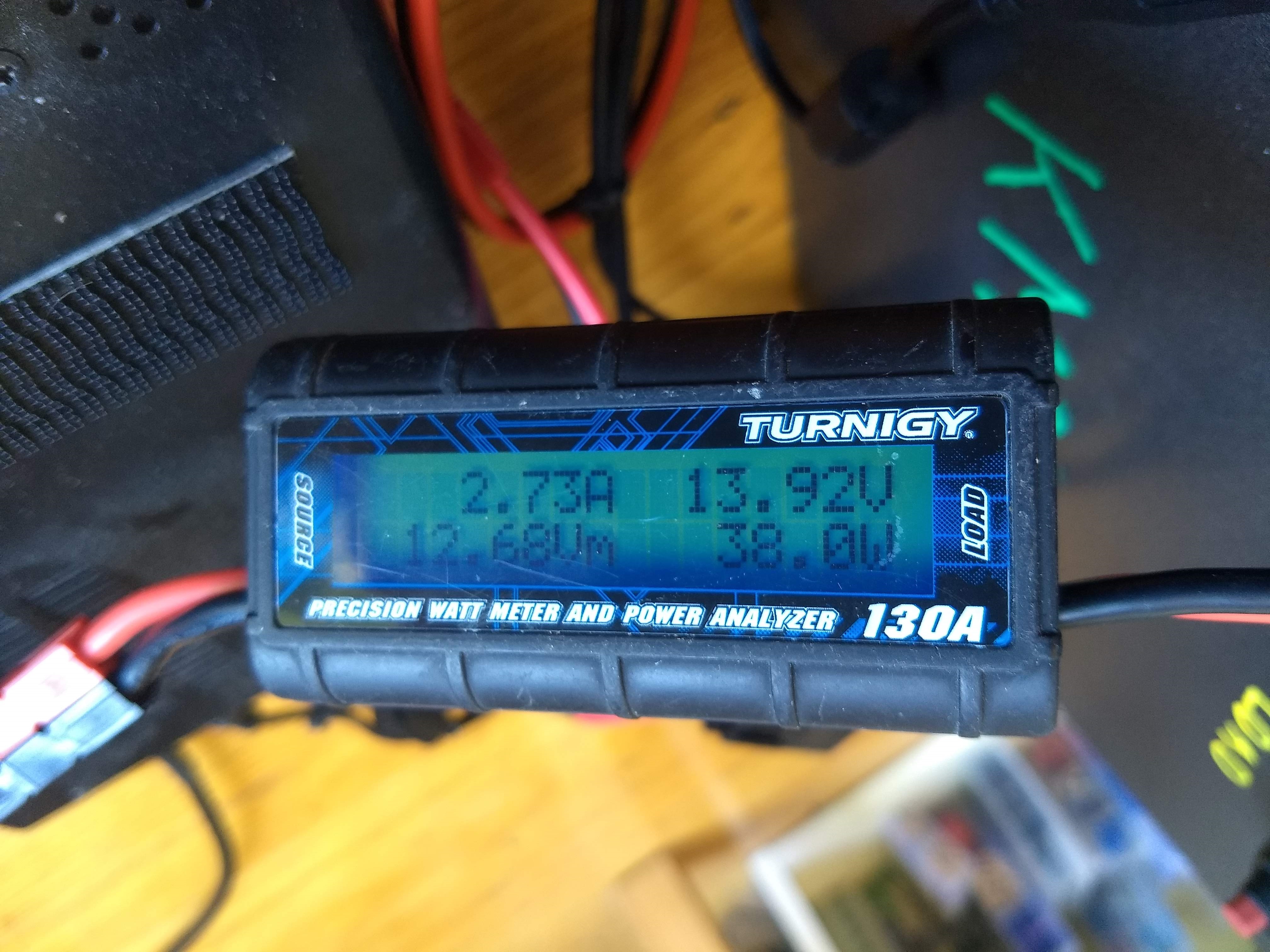
I’ve connected an in-line power meter, which shows that my panel is providing 38 watts. Whatever power is not consumed by loads goes into recharging the battery.
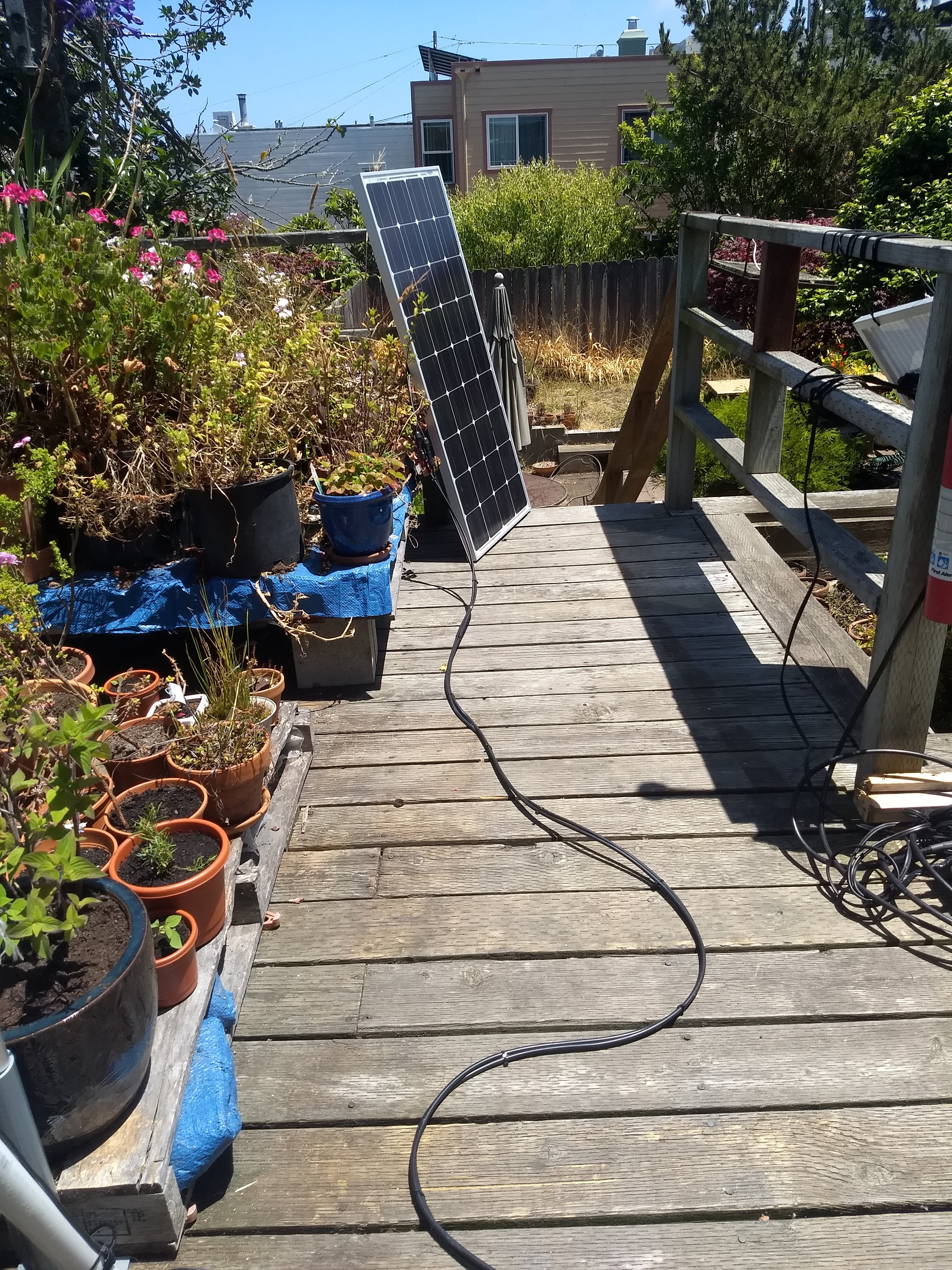
This is one of my solar panels. It is rated for 100 watts maximum, in direct sunlight. At some point I will buy a folding panel that is easier to transport to the field.
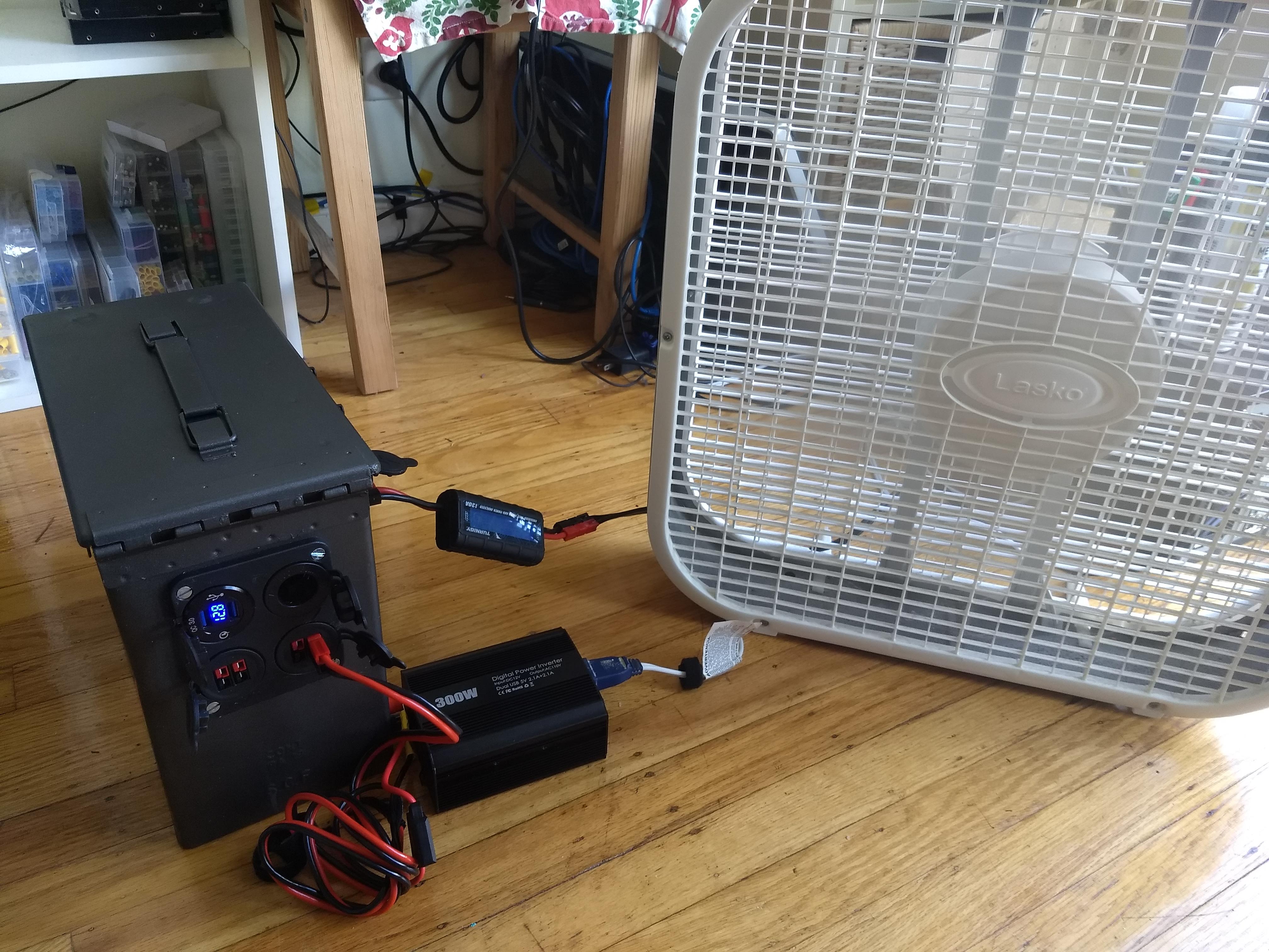
Most of the devices I want to use in the field run from 12V DC. But I can also run AC devices using an inverter. How about a solar-powered box fan on a hot day at the campsite? It draws a lot of power (60 watts on low speed) but it does work!
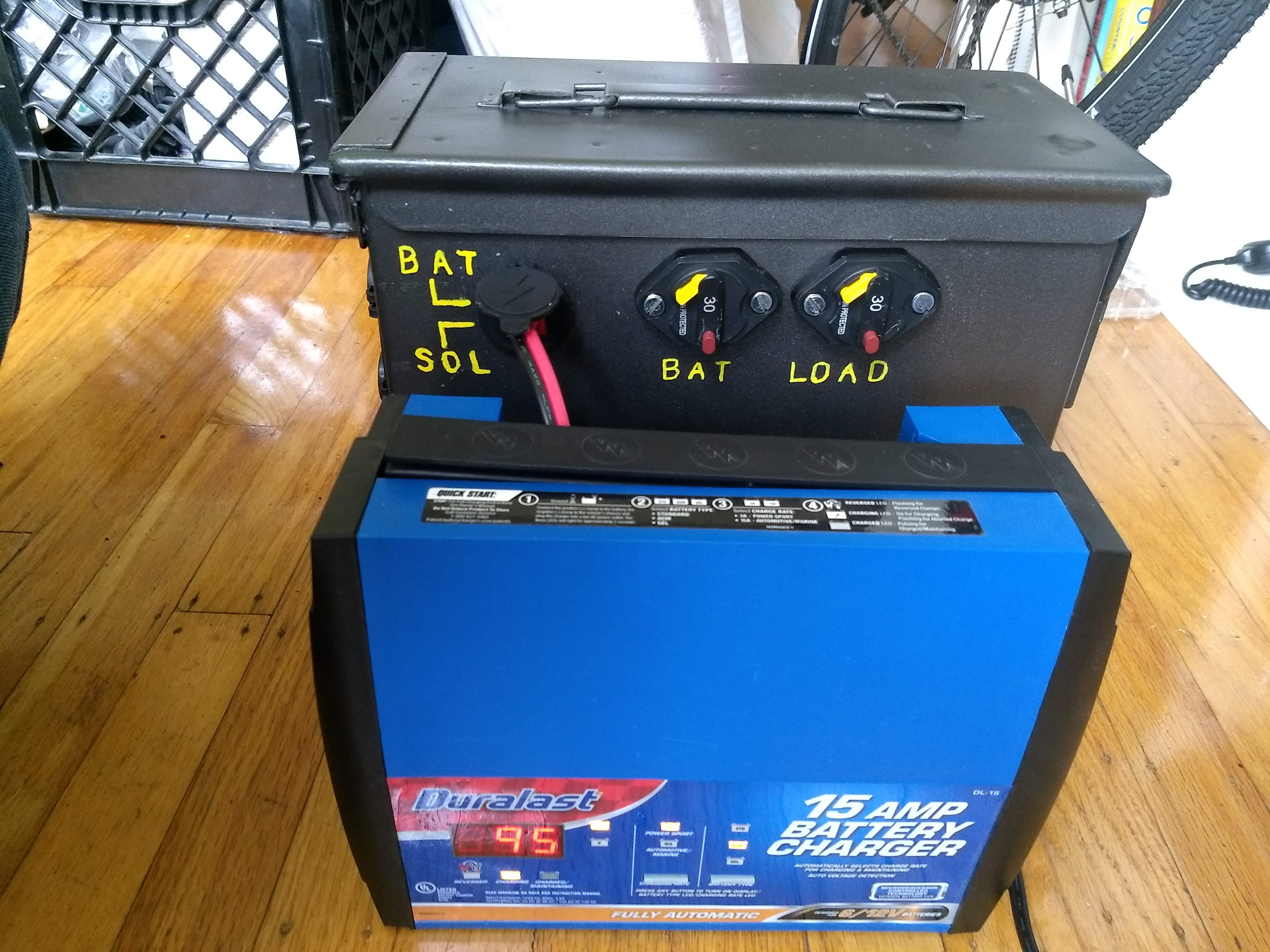
To charge the box from wall power, I use a battery charger from the auto parts store, modified with a Powerpole connector. The charger connects to the “BAT” side of the power input port. This bypasses the solar charge controller and connects directly to the battery through a 30 amp fuse. In this configuration, both circuit breakers need to be switched off.
Capacity test
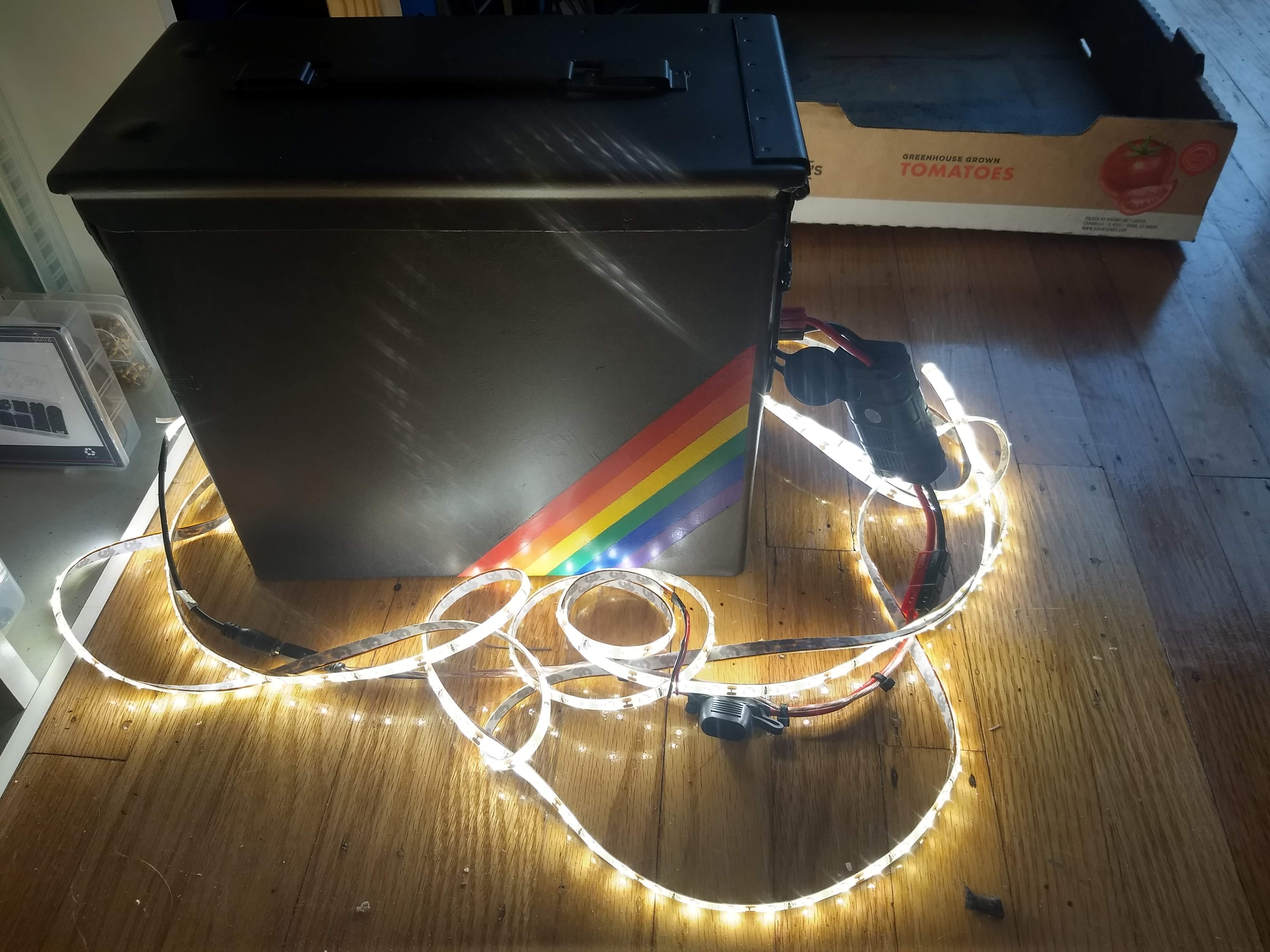
The big question is, how long will this battery run my equipment? I did an experiment using a 5 meter LED light strip as a test load.
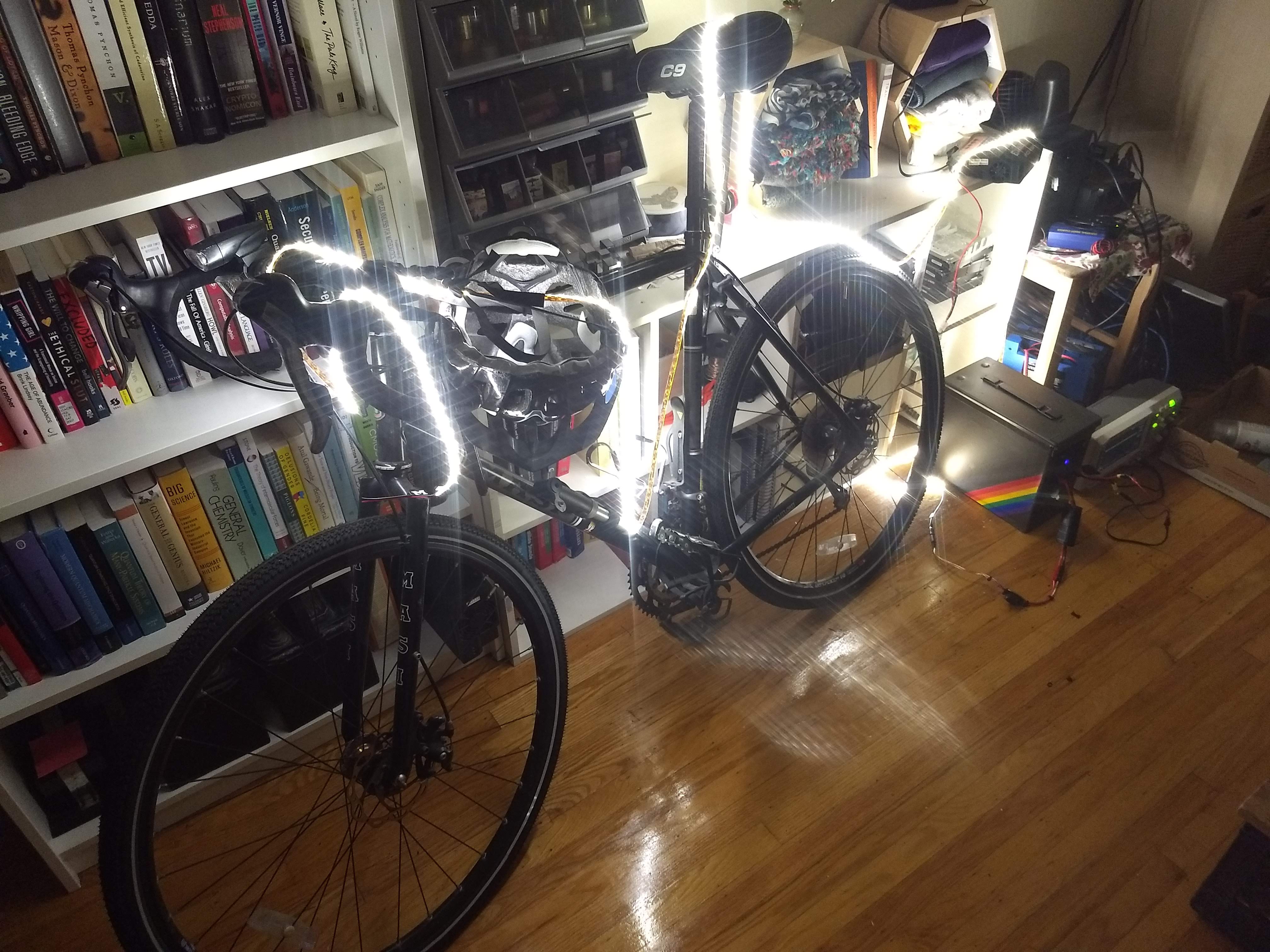
In an emergency this would provide all the light I need for my living room. It also makes a nice decoration for my bicycle. :) The lights drew 1 A (± 10%) of current throughout the test. Since the battery is rated for 35 Ah, this corresponds to a C-rate of 1/35 ≈ 0.029 C.
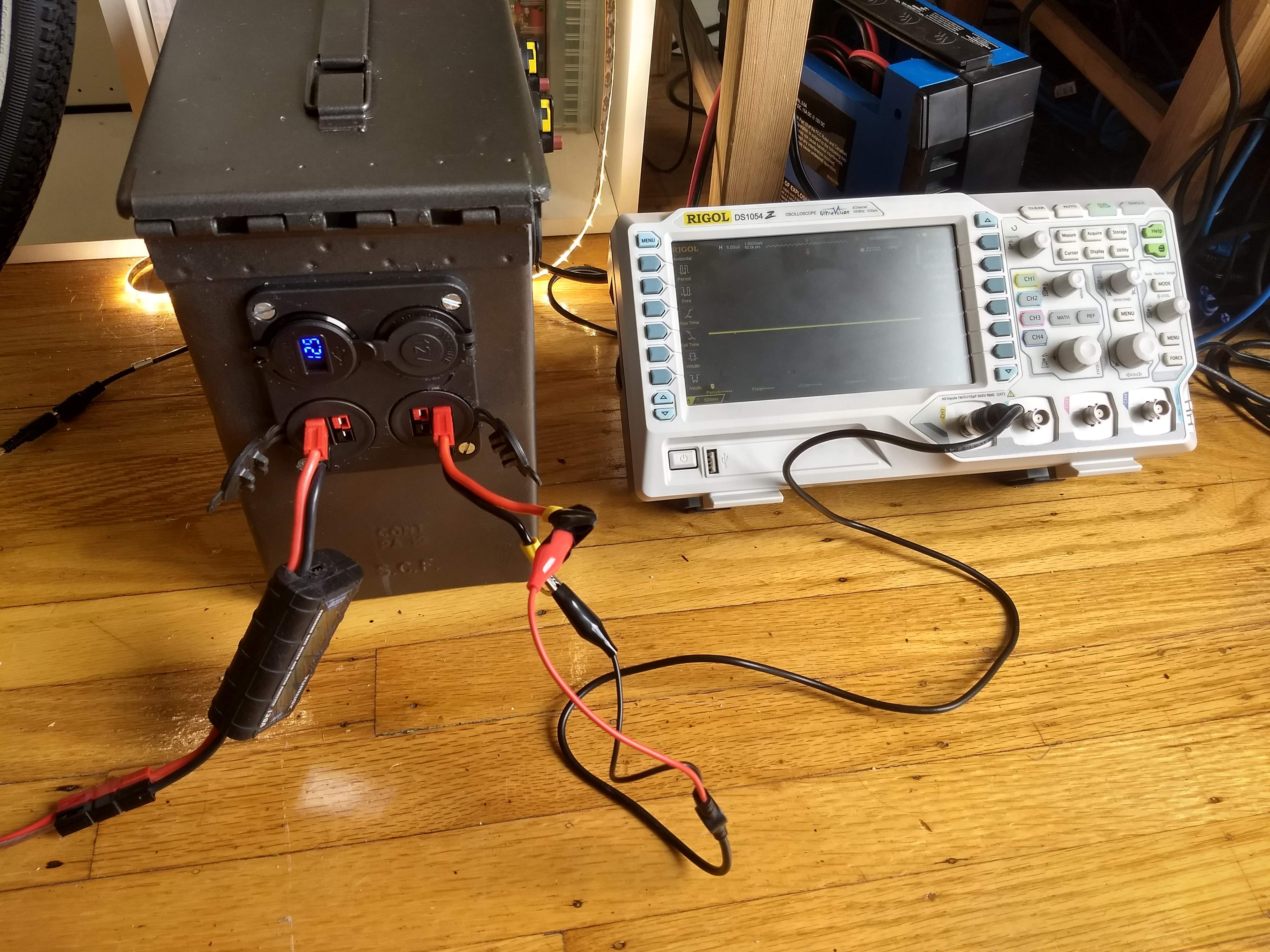
I measured the voltage over time using my Rigol DS1054Z oscilloscope. The scope has an Ethernet port and I was able to query the voltage over the network using a small Python script.
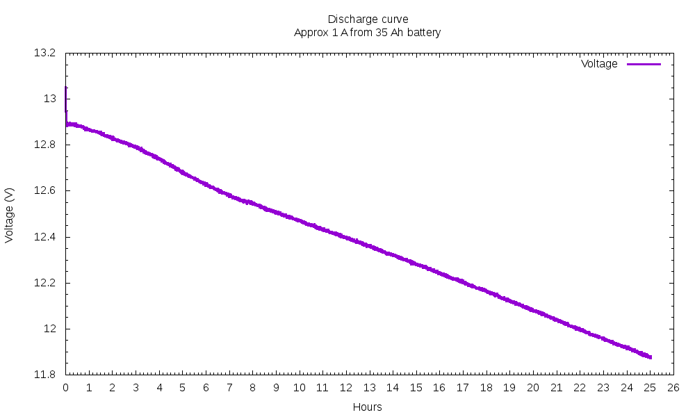
Ignoring the fast drop in the first few minutes, the voltage decreased steadily from 12.9 to 11.9 over the course of 25 hours. The linear graph is expected, because we did not get close to exhausting the battery’s stored energy. At some point though, the discharge curve goes nonlinear and the voltage starts to drop rapidly. I don’t have a datasheet for my battery, but this one is similar.
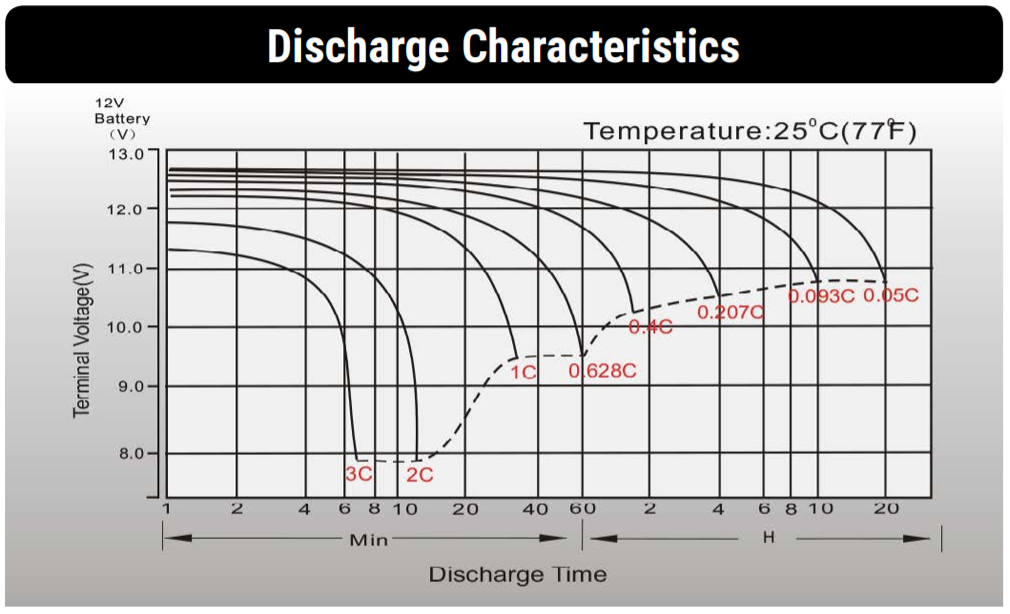
Let’s look at the 0.05C curve. It hits 11.9 volts after approximately 12 hours, and 10.8 volts at 20 hours. I’ll consider 10.8 to be fully discharged; going any lower would likely damage the battery. Extrapolating to my experiment suggests I could run this 1 amp load for almost 42 hours. This is not a rigorous calculation, but it confirms that the nominal rating of 35 amp-hours is realistic for a 1 amp load.
At a higher discharge rate, I will get less total energy. And it’s less stressful on the battery if I don’t go as low as 10.8 volts. Anyway, this shows that I could run my LED lights for several evenings, or use my HF radio all day, without any solar charging.
Internals
Here’s the wiring diagram:
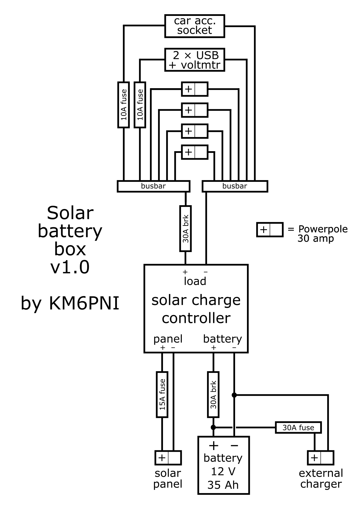
I used circuit breakers on the battery and load connections, because I expect that plugging in excessive loads will be the most likely cause of overcurrent. The breakers are externally accessible and also function as the power switches for the whole box. The internal fuses are not going to blow unless a component fails or I plug something in wrong.
The charge controller will protect the battery from damage due to over- or under-voltage. I have the low voltage threshold set at 11.0 volts, which is a safe though not terribly friendly discharge point.
The connector labeled “external charger” allows direct access to the battery terminals. Besides charging from the wall, this has several other uses:
- I can check the battery voltage when the box is off.
- In case a breaker or the charge controller fails, I can run a load directly from the battery.
- I can place an external battery in parallel with the internal one. There are some problems that can occur when doing this, but it would be useful in a pinch.
- By adding one internal switch, I could isolate the internal battery and run the box from only an external battery.
Despite my attempts to cut wires short, the inside is a bit of a rat’s nest.
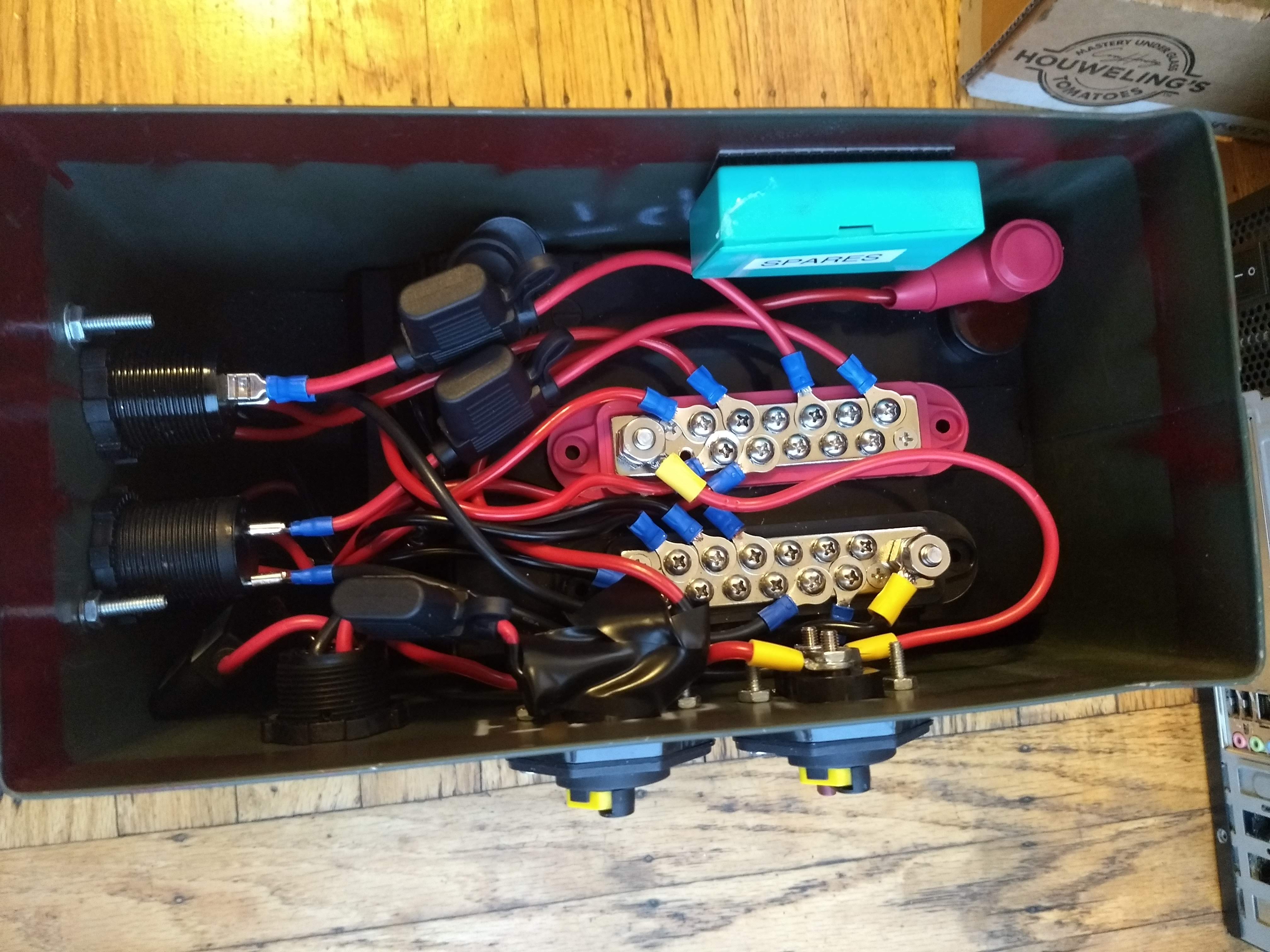
I mounted the busbars on top of the battery using heavy-duty Velcro. The battery is also attached to the ammo can using Velcro. The charge controller is basically not visible in this photo; it’s situated vertically to the left of the battery, with some foam to fill empty spaces and prevent things from sliding around. I included storage for spare fuses (small box at top right).
Building it
Bill of materials:
- Military surplus ammo can from Alameda Army Navy Surplus. Approximately 6”W × 12”L × 10”D exterior dimensions. This one was used for aircraft flares.
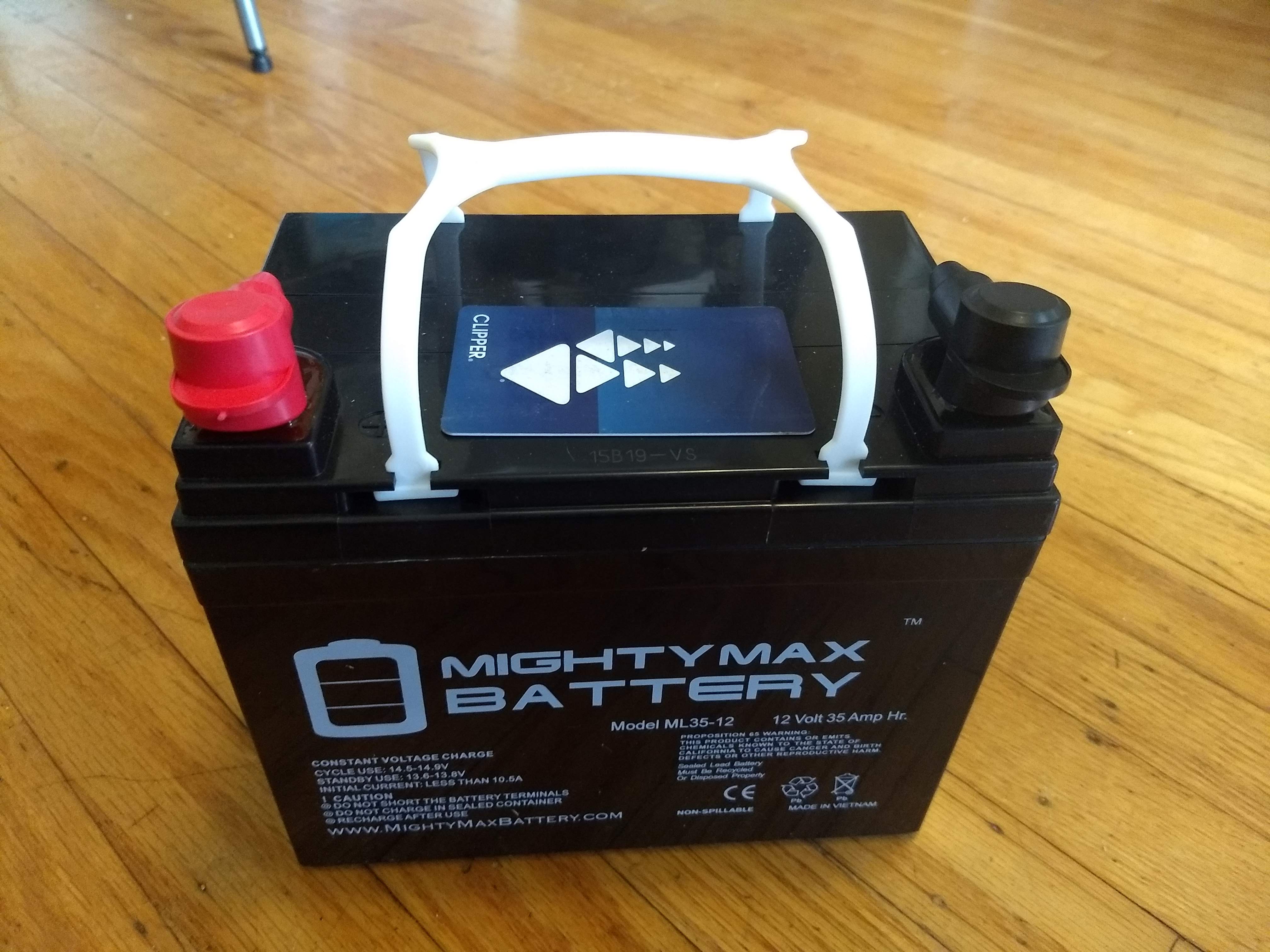
- ML35-12 12V 35Ah AGM battery
- Busbar pair, which included the battery terminal covers
- 30A MPPT solar charge controller from a previous project
- 3 × panel mount Powerpole housing
- Panel mount dual USB QC 3.0 + voltmeter. Similar units are available with USB-C. However, they can’t provide enough power to charge my laptop, which is why I got the external brick.
- Panel mount car accessory socket
- Square panel-mount plate
- 2 × 30A circuit breaker
- 4 × 12 AWG automotive-type fuse holders and fuses
- Plastic box for spare fuses (from a bike tube repair kit)
- Lots of 12 AWG wire and crimp connectors
- Miscellaneous hardware
- Car battery charger
Total cost, not including the solar panel, was around 300 USD. This is cheaper than a comparable AGM battery box from Goal Zero, although lacking a few of its features.
Here is the battery, with card for scale:
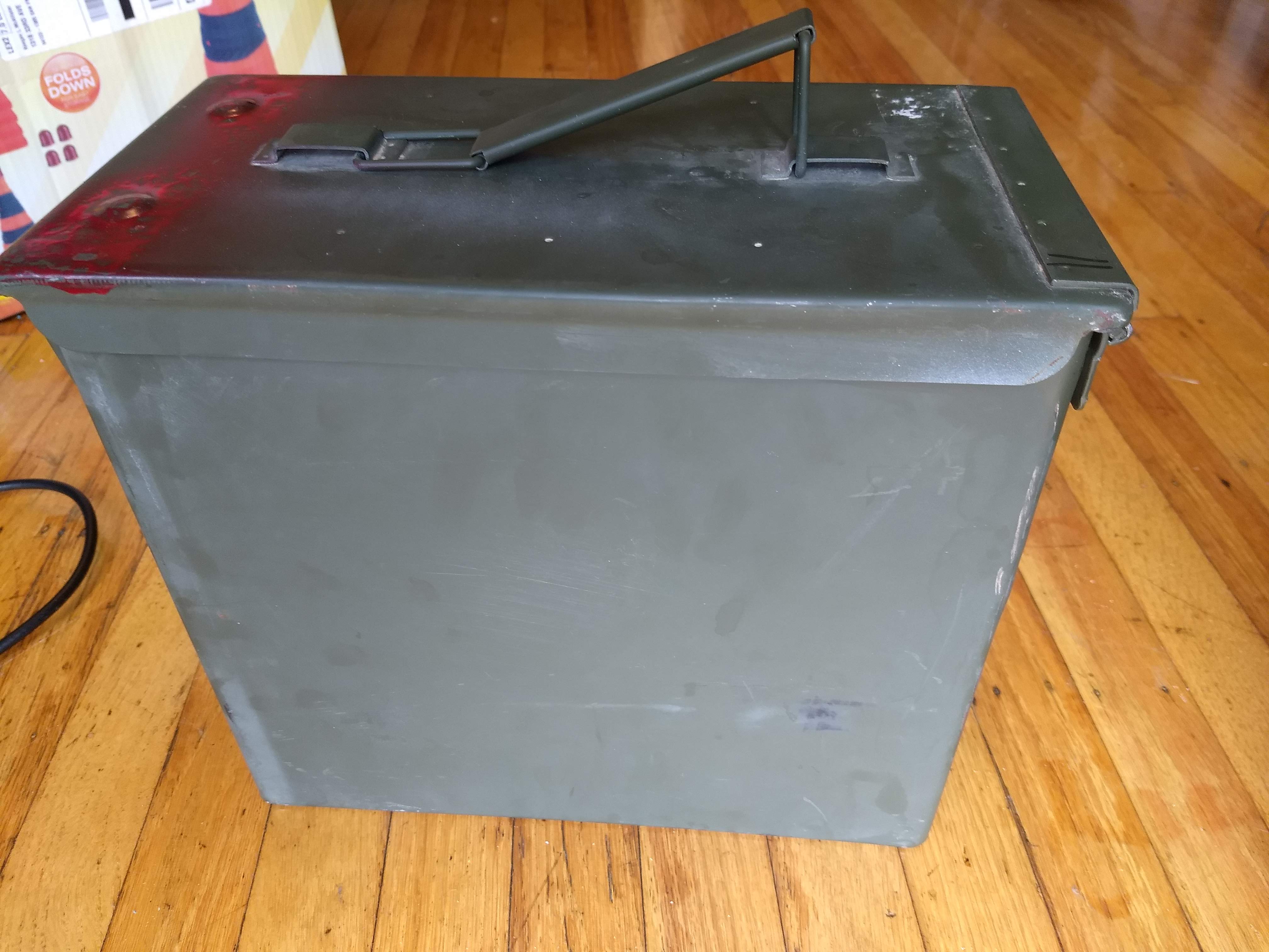
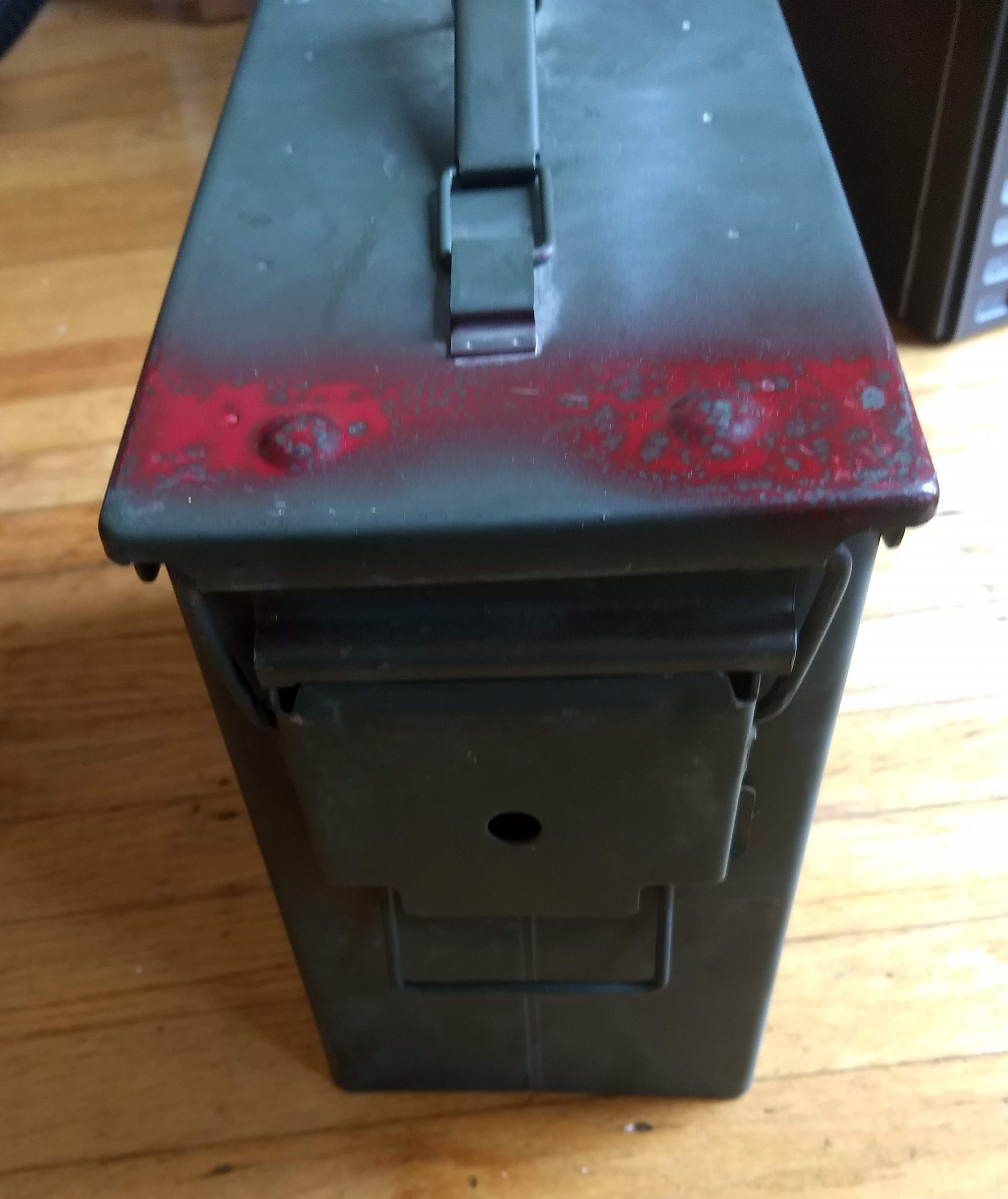
When I got the ammo can it looked like this:
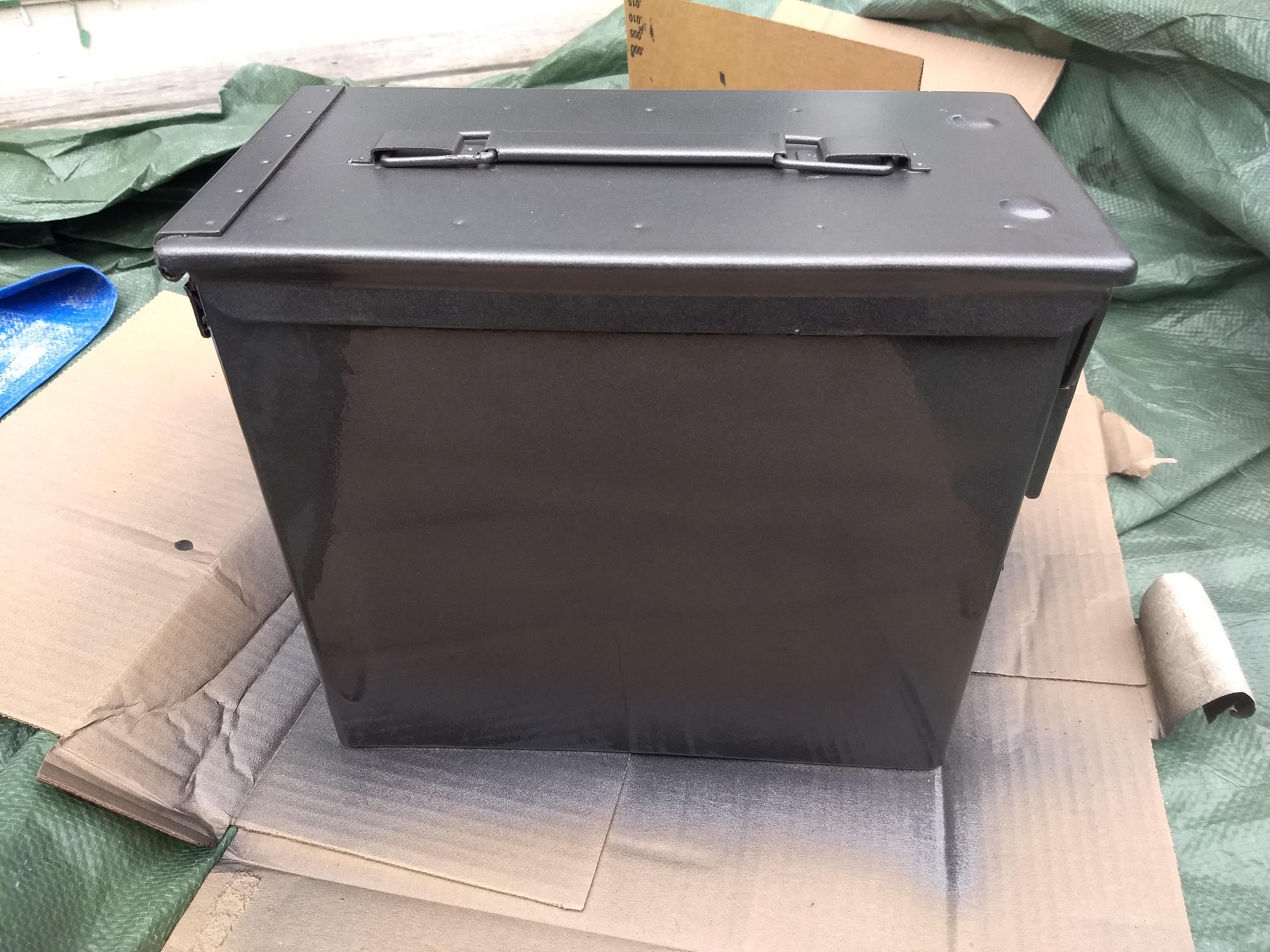
I decided to spruce it up with some Rust-Oleum Universal Flat Soft Iron spray paint. Nice and shiny, waiting for the paint to dry:
I had to do some stripping, sanding and re-painting to fix some areas that didn’t come out smooth the first time. It’s still not a perfect paint job but good enough for me!
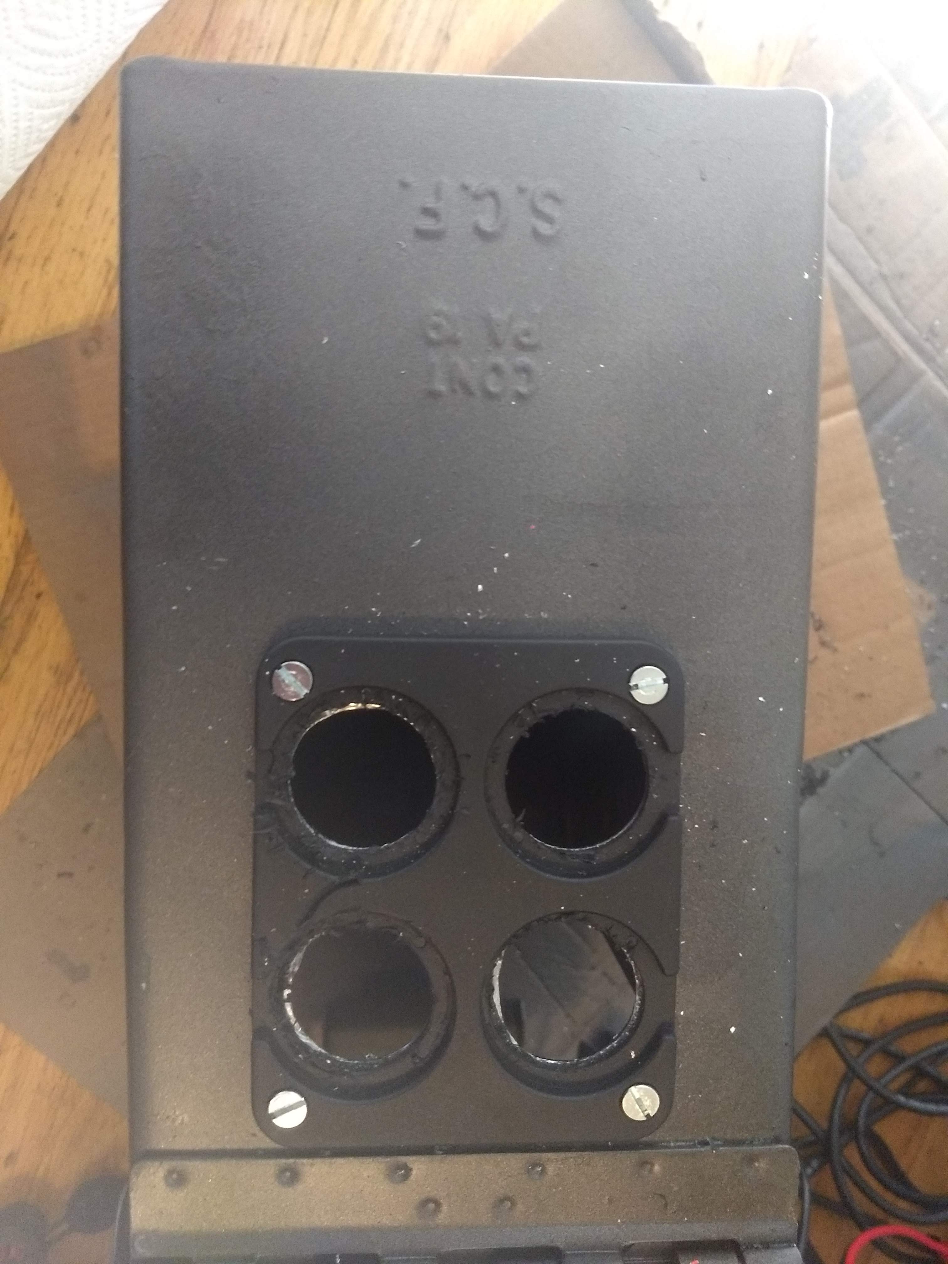
I installed the plastic panel-mount plate and then drilled the large holes with a 1 1/8” hole saw. I’m not that great with the hole saw and I ended up chewing up the plastic plate a bit. But most of it isn’t visible once the components are installed, and I still think cutting with the plate on was a good idea to ensure the proper fit.
As you may have noticed, I installed the plate sideways. This was deliberate, because I wanted the protective covers to open to the sides and not top/bottom. However, I didn’t realize until later that this meant the voltmeter would be sideways too. Oh well.
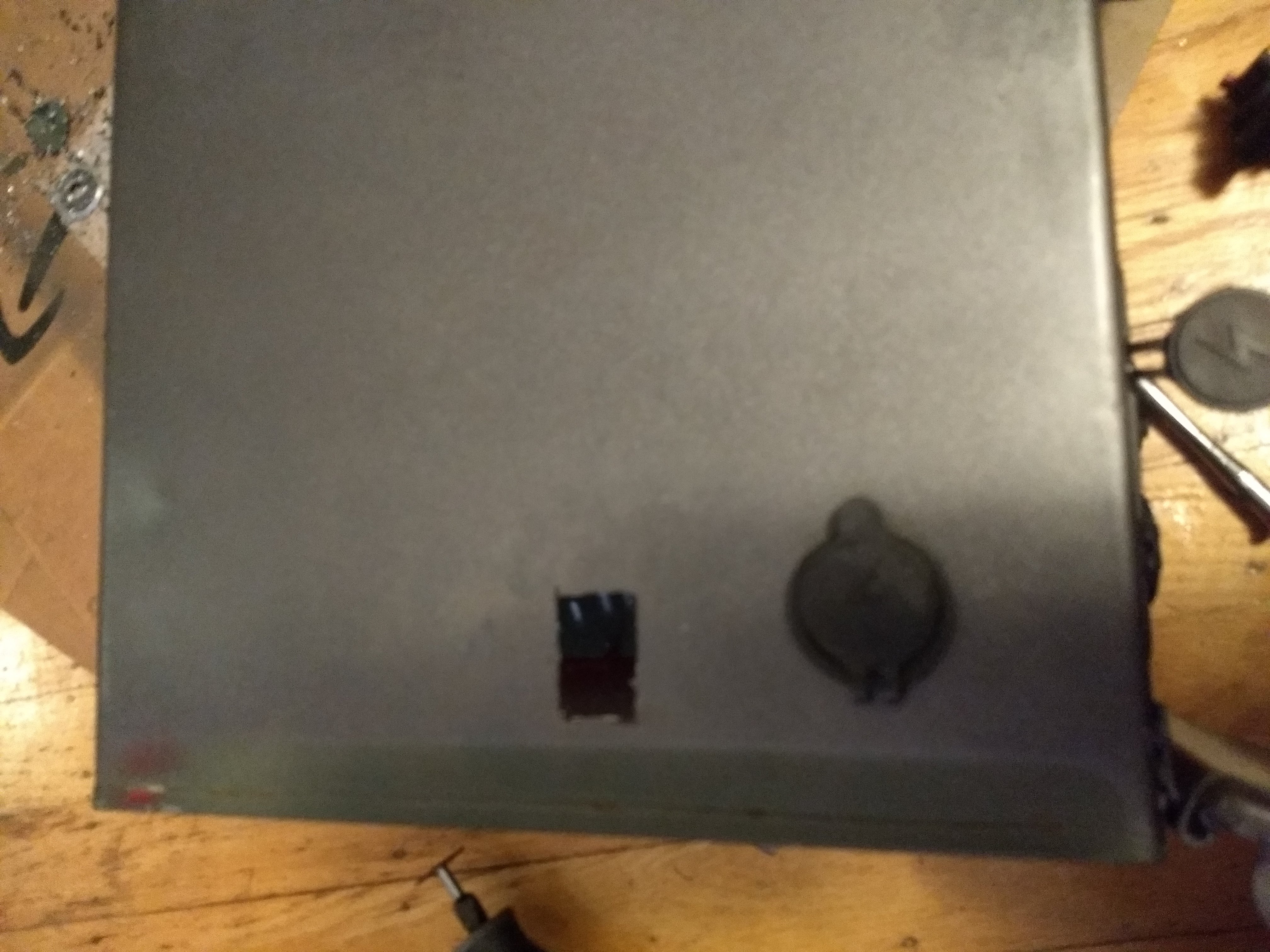
I used a Dremel to cut rectangular holes for the breaker terminals:
Here’s the charge controller before installation.
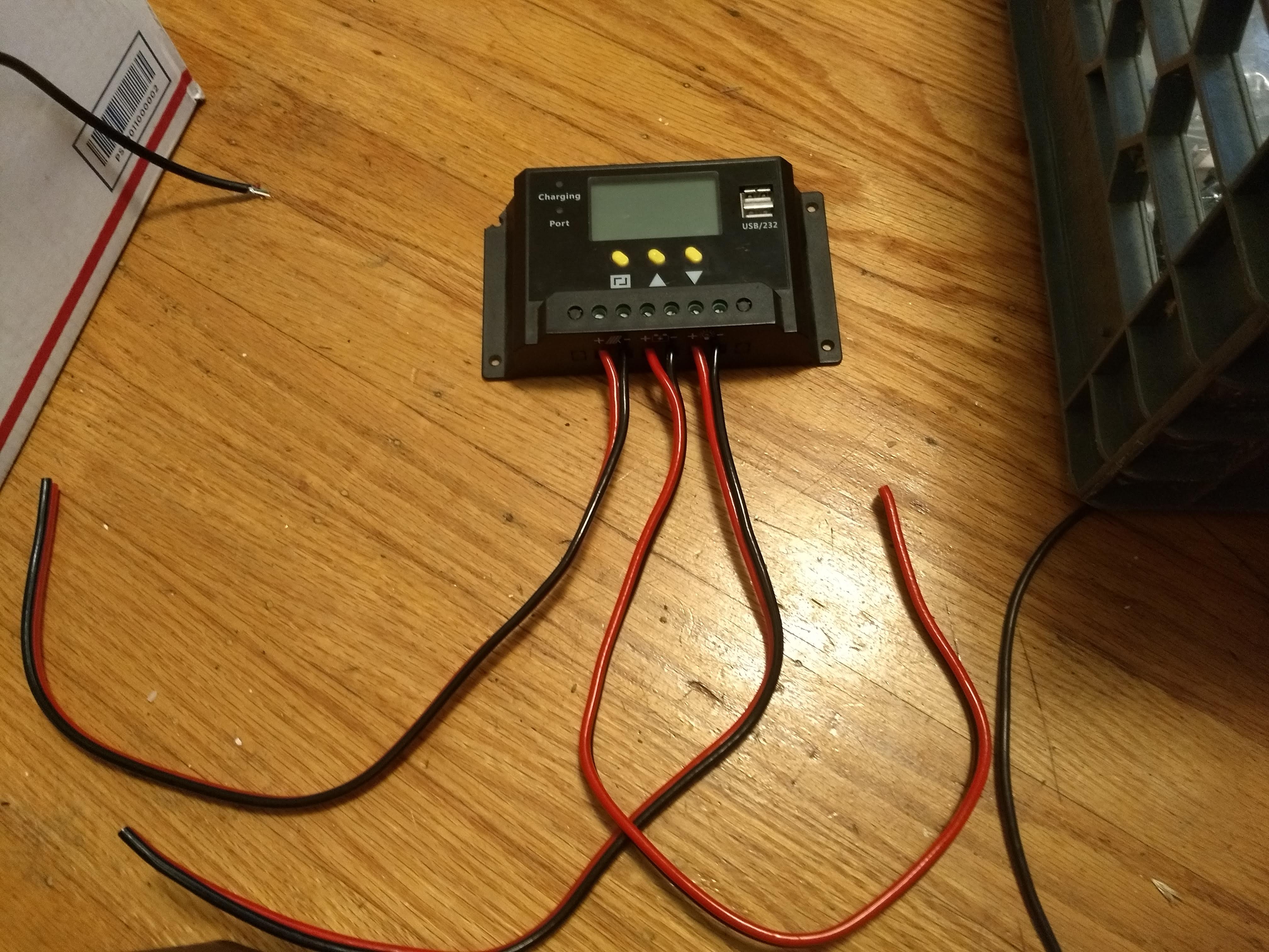
I trimmed those leads as part of wiring everything up.
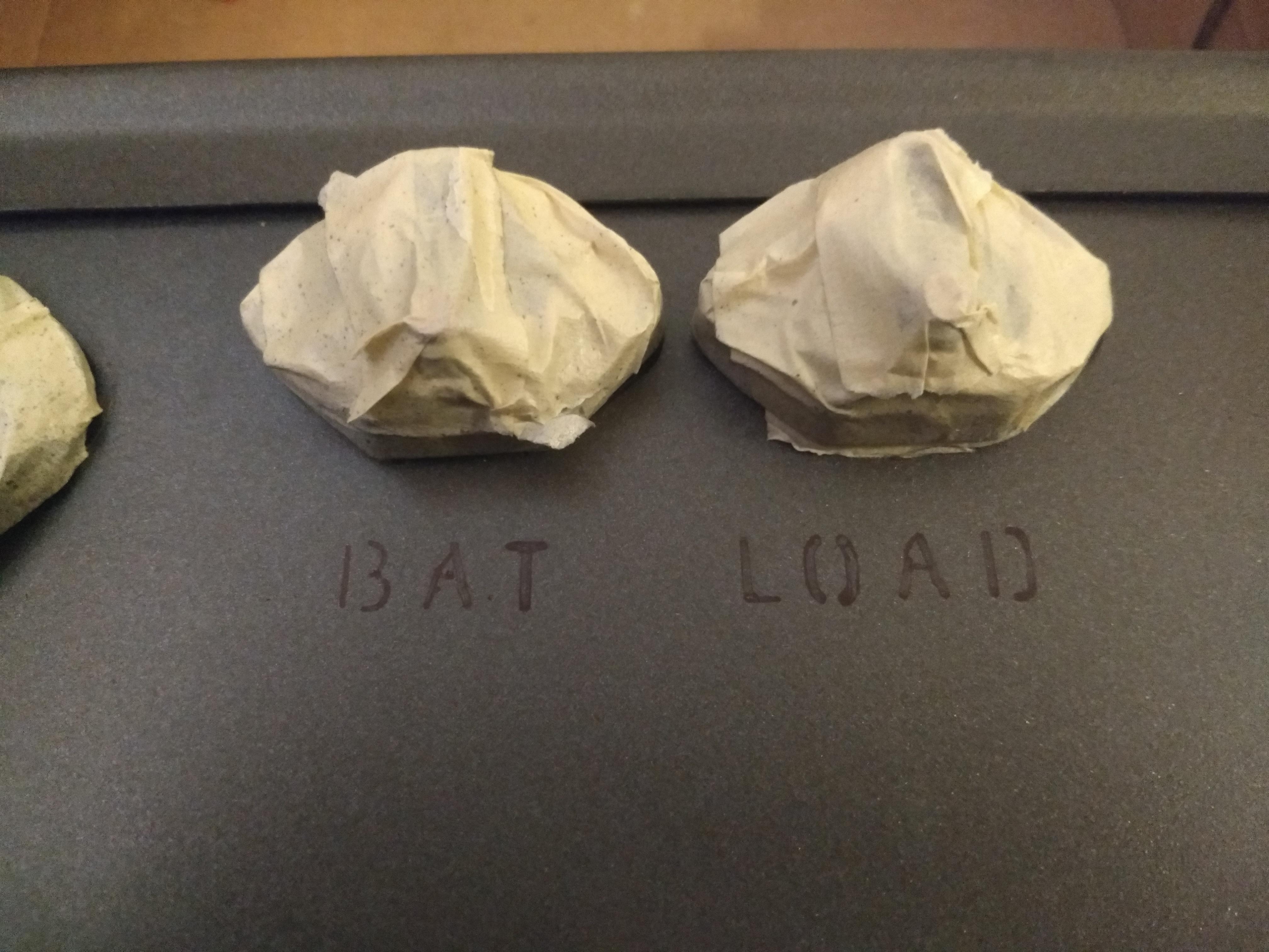
Once everything was installed and working, it was time to finish painting. I wrote the labels with Sharpie using a stencil, and then went over them freehand with an acrylic paint pen.
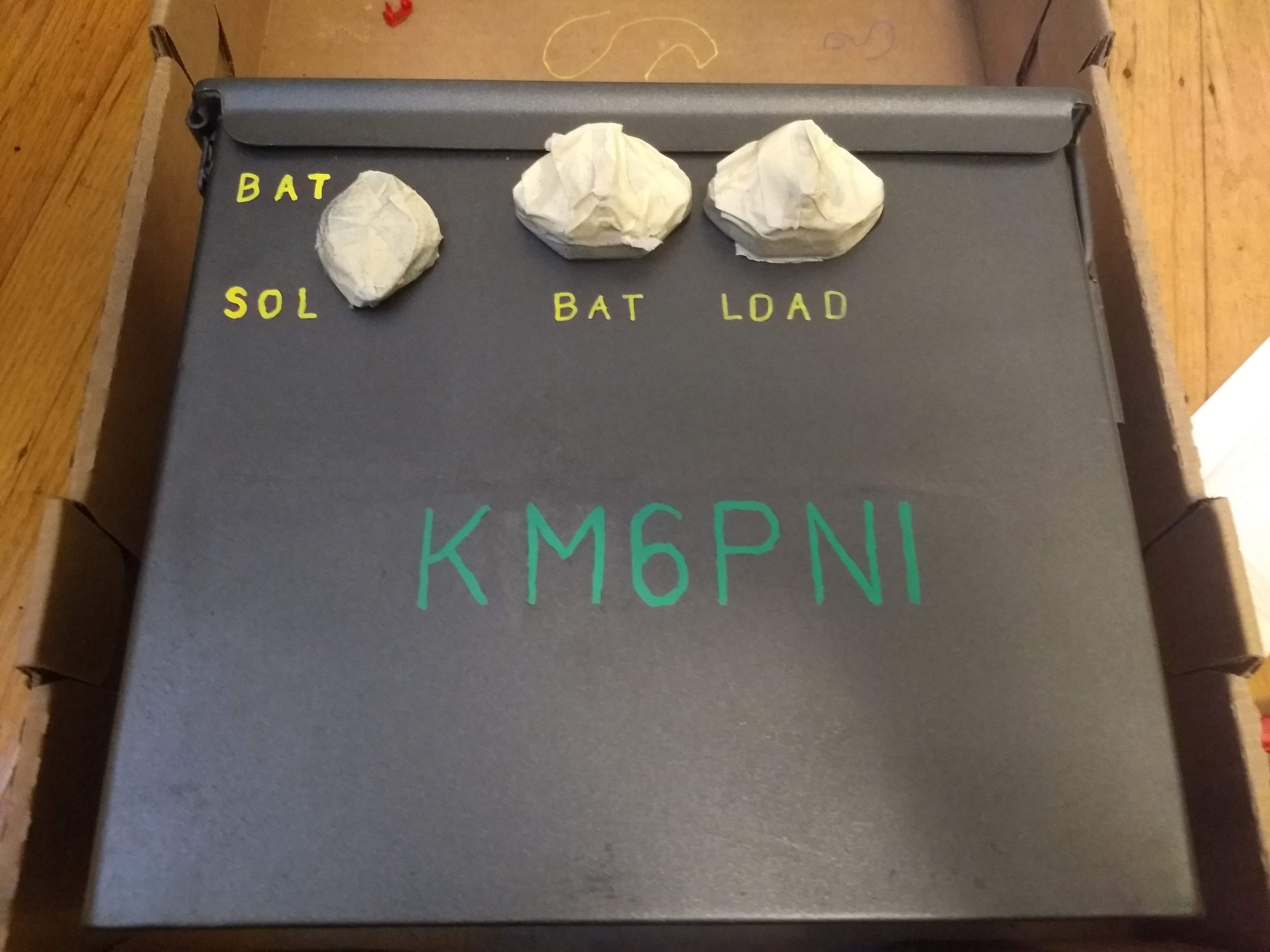
The connectors are masked off so I can spray the whole thing with a clear coat finish. However, I found that the clear coat stripped the spray paint in some places, which required further touch-ups. (Of course it hadn’t done this on my test sample with the same metal and paint….)
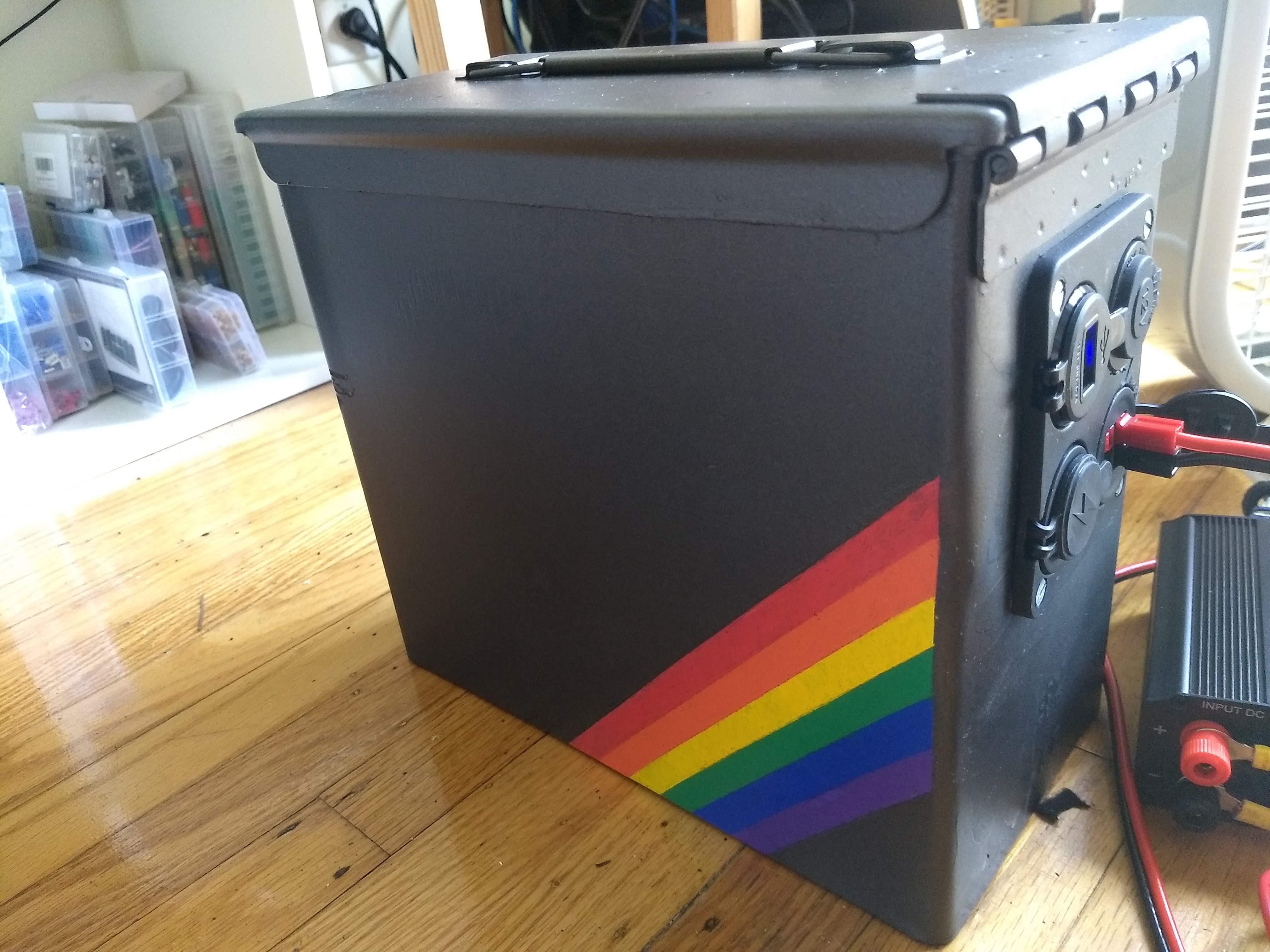
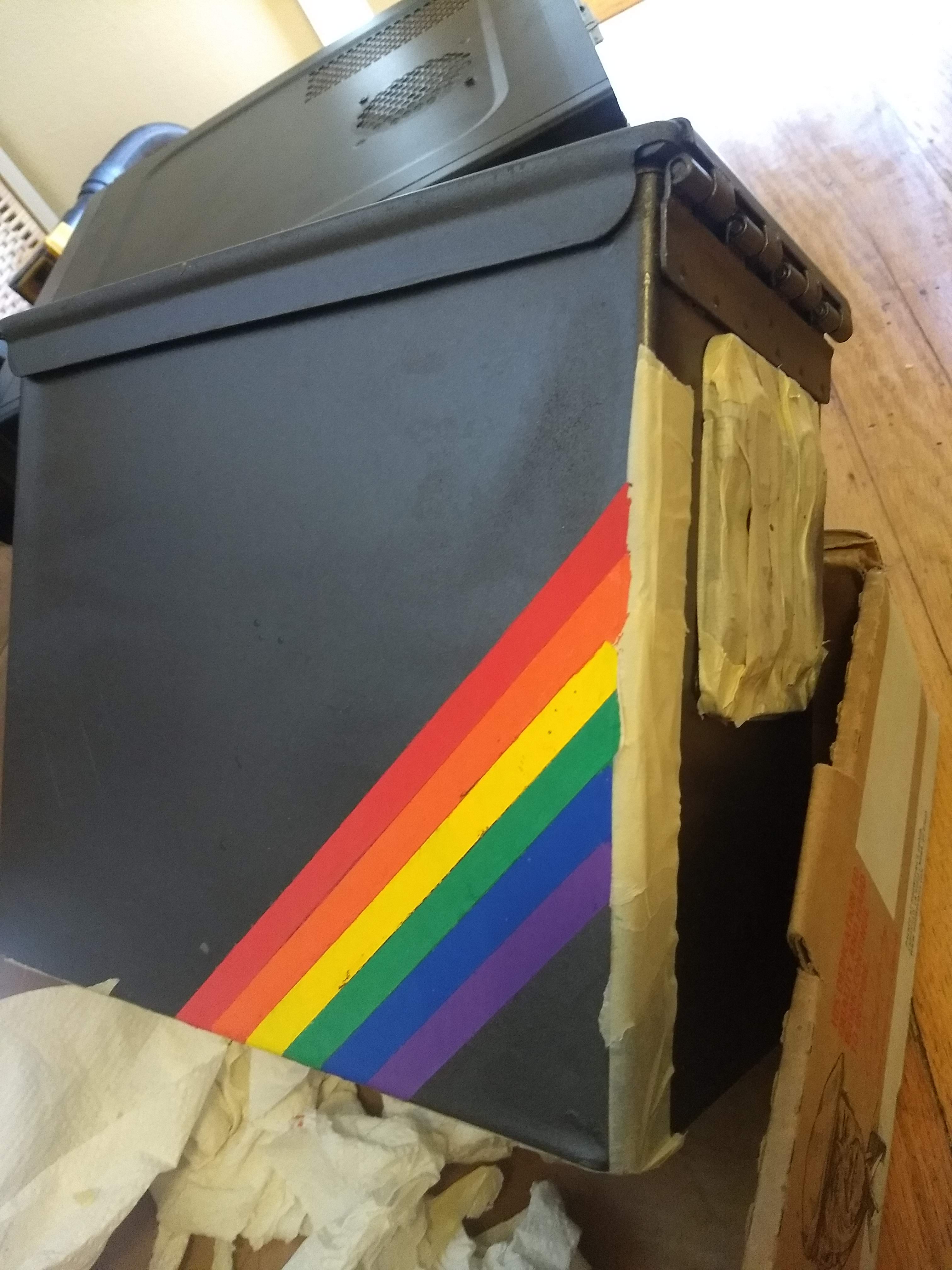
On the other, blank side I wanted to add a little decoration, so I painted a diagonal rainbow, vaguely inspired by the ZX Spectrum.
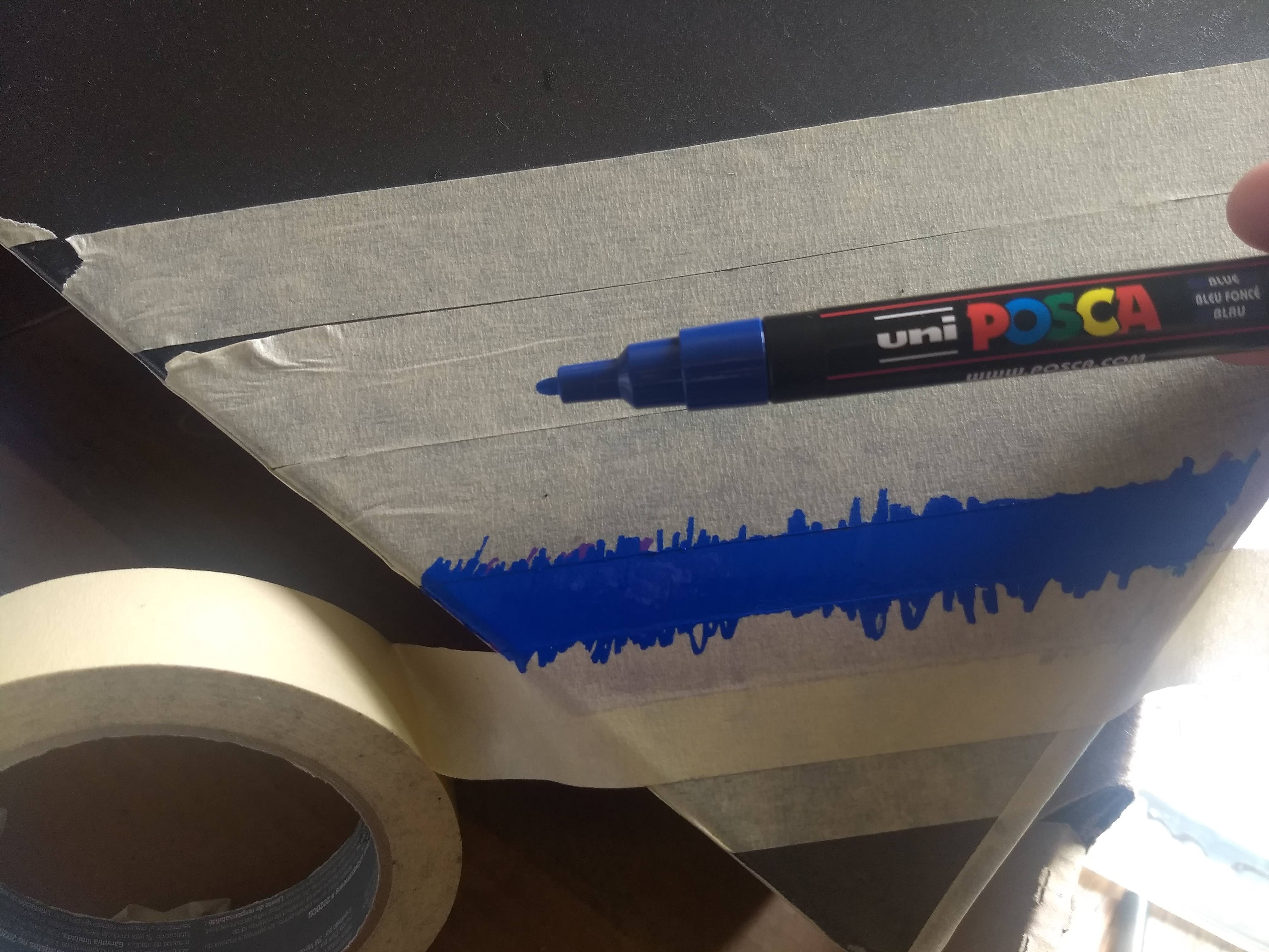
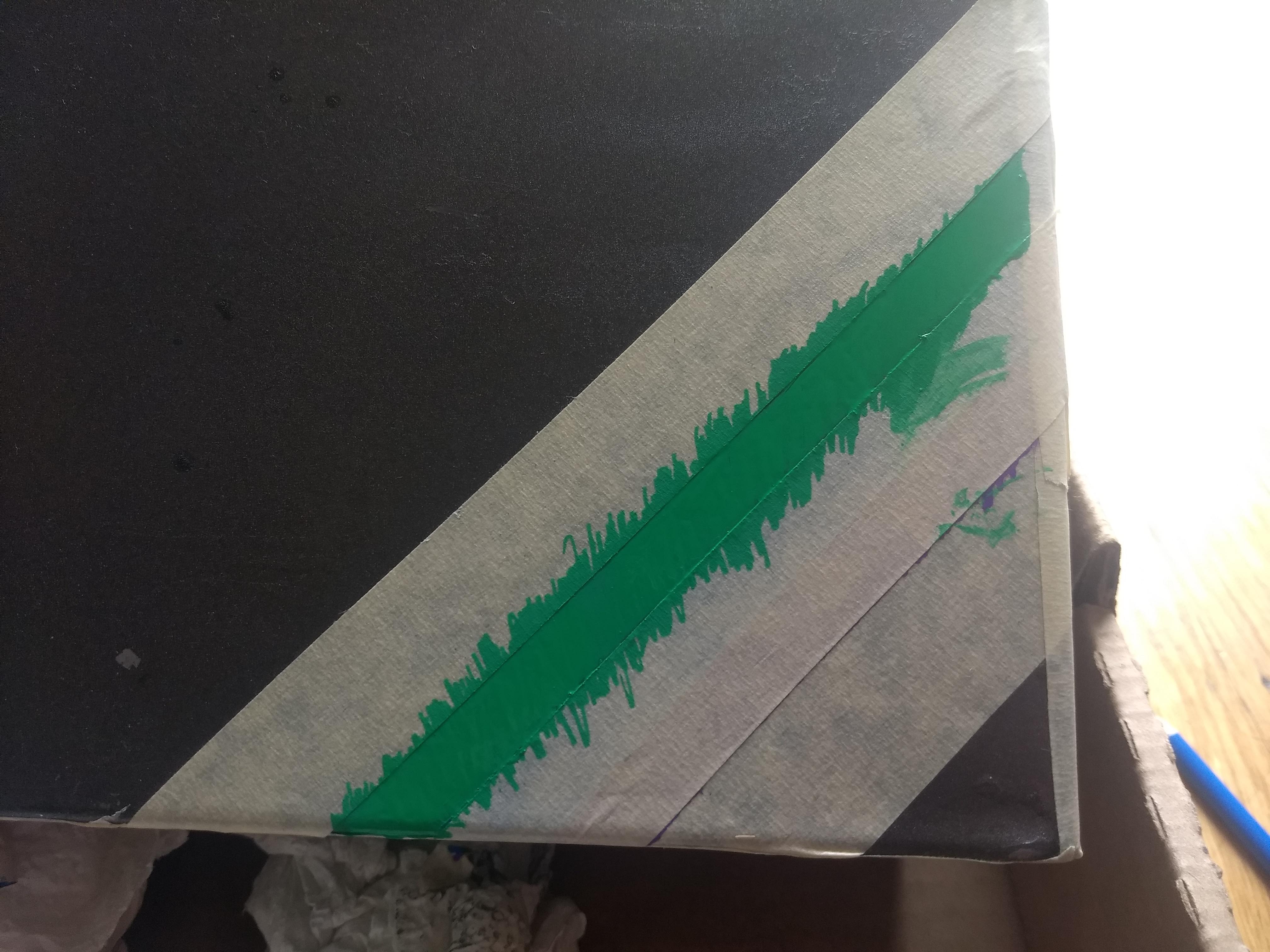
Rainbows are pretty, and I did this project mostly during Pride month here in San Francisco so I guess I had rainbows on my mind!
I clear-coated this side too. This is actually where I had the most trouble with spray paint coming off. So I repainted the metalic grey after that happened, and clear-coated just the acrylic rainbow stripes. All told there was a lot of painting, masking, cleaning, re-painting, and waiting, but I’m really happy with the result!
Further thoughts
I chose a lead-acid battery because they are cheap, easy to work with, and durable. The downside is that they’re heavy! The whole box weighs 30 pounds. I can carry it a few blocks to and from my car, but I wouldn’t want to hike a mile with it. I have some lithium iron phosphate cells that I may work into another battery box or an upgrade to this one.
Because of the weight, carrying this box by the attached metal handle is not too comfortable. My wife (also a ham) is going to make a leather cover for the handle.
The circuit breakers stick out from the side of the box, and can be damaged if the box bumps into stuff. I already had to replace a breaker that I broke during construction. I plan to add some kind of shield but haven’t decided on a design yet.
That’s it! Hope you enjoyed my first post, and stay tuned for more projects!